


EDMMT712101
Installation Manual
VAM-HVE/HVLT Series
127
3P645058-1
5
English
DUCT
CONN
E
CTION
5
DUCT
CONN
E
CTION
5
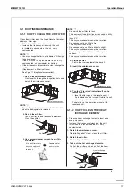
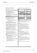
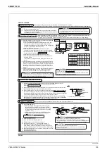
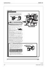
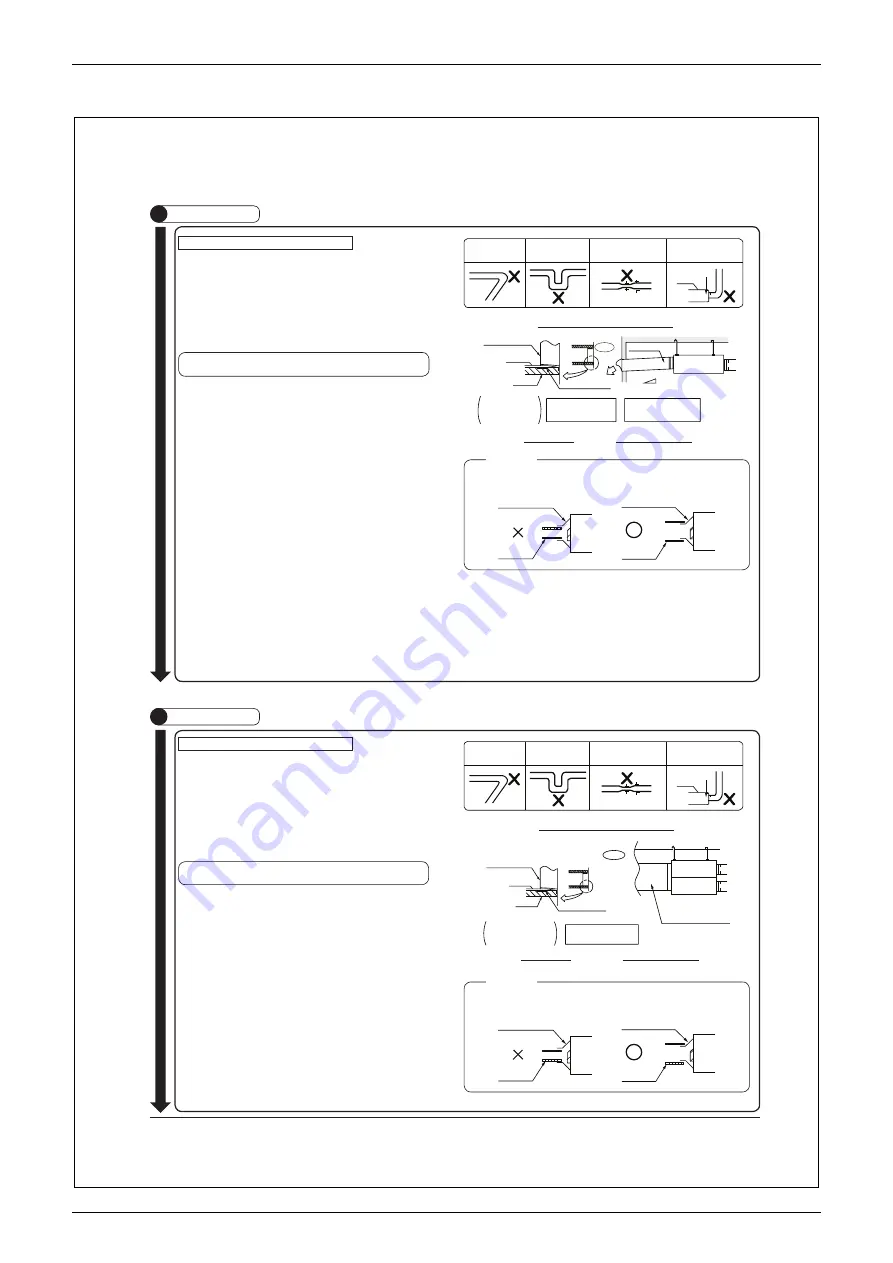
Follow the instructions below to connect ducts.
y
Use the duct applicable to the model of the unit used.
y
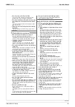
Do not connect ducts as shown in the figure on the right (Examples of prohibited duct
connection).
y
Follow the minimum bending radius for flexible ducts specified in the catalog of the
flexible ducts used.
y
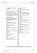
To prevent air leakage, wind aluminum tape around the section after the duct
connector and the duct are connected
①
.
y
Be sure to insulate the ducts and duct connectors
①
(accessory) to prevent condensation.
(Material: Glass wool of at least 25mm thickness).
In cold areas where outside temperature falls below -10°C, provide
insulation for the indoor duct (SA) to prevent condensation.
y
If the level of temperature and humidity inside the ceiling is constantly high, be sure to
install ventilation equipment inside the ceiling.
y
Install the two outdoor ducts (intake and exhaust) with a downward slope (slope of
1/30 or more) to prevent entry of rainwater.
y
Insulate the duct and the wall electrically when a metal duct is passed through a
metal lattice, wire lattice, or metal lining of a wooden structure.
y
Do not use a bent cap or a round hood as the outdoor hood because it might get wet
in rain directly.
In this case, we recommend using a deep hood (optional accessory).
y
When using a deep hood, make sure the duct from the deep hood (outer wall) to the
unit is at least 1m long.
y
Set the pitch between the exhaust air outlet (EA) and the outside air intake (OA) on
external wall to 3 times the duct diameter.
y
If windows and road lighting equipment are close to the air intake (OA) of suburban
buildings and insects tend to swarm around the light, minute insects intruding from
outside air intake (OA) may enter into indoor spaces through the air filter.
In such cases, consider full-scale anti-insect measures, such as a filter box (to be
locally procured), in the design stage.
y
Attach the indoor air exhaust grill (SA) and the indoor air intake grill (RA) in a location
where short circuit will not occur.
y
Using flexible or silent ducts as the duct to be connected to the indoor air outlet (SA)
can be effective in reducing air exhaust noise.
Select materials considering the fan speed required for the unit’s application and
noise/sound levels. Refer to the technical documentation for the selection of material.
y
Be sure to locate the indoor air supply grille (SA) and the indoor exhaust air grille
(RA) in the same living space.
Locating them in different living spaces can cause noises coming from the gap in the
door or smells moving between sections. It can also cause the doors to open and
close by themselves or make the door difficult to close.
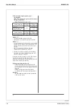
Follow the instructions below to connect ducts.
y
Use the duct applicable to the model of the unit used.
y
Do not connect ducts as shown in the figure on the right (Examples of prohibited duct
connection).
y
Follow the minimum bending radius for flexible ducts specified in the catalog of the
flexible ducts used.
y
To prevent air leakage, wind aluminum tape around the section after the duct
connector and the duct are connected
.
y
Be sure to insulate the ducts and duct connectors
①
(accessory) to prevent
condensation.
(Material: Glass wool of at least 25mm thickness)
In cold areas where outside temperature falls below -10°C, provide
insulation for the indoor duct (SA) to prevent condensation.
y
If the level of temperature and humidity inside the ceiling is constantly high, be sure to
install ventilation equipment inside the ceiling.
y
Insulate the duct and the wall electrically when a metal duct is passed through a
metal lattice, wire lattice, or metal lining of a wooden structure.
y
If windows and road lighting equipment are close to the air intake (OA) of suburban
buildings and insects tend to swarm around the light, minute insects intruding from
outside air intake (OA) may enter into indoor spaces through the air filter.
In such cases, consider full-scale anti-insect measures, such as a filter box (to be
locally procured), in the design stage.
y
Attach the indoor air exhaust grill (SA) and the indoor air intake grill (RA) in a location
where short circuit will not occur.
y
Using flexible or silent ducts as the duct to be connected to the indoor air outlet (SA)
can be effective in reducing air exhaust noise.
Select materials considering the fan speed required for the unit’s application and
noise/sound levels. Refer to the technical documentation for the selection of material.
y
Be sure to locate the indoor air supply grille (SA) and the indoor exhaust air grille
(RA) in the same living space.
Locating them in different living spaces can cause noises coming from the gap in the
door or smells moving between sections. It can also cause the doors to open and
close by themselves or make the door difficult to close.
y
Attach the connection chamber (optional accessory) according to its installation manual.
Extreme bend
Multi bend
Signifi cantly reduce the diameter
of the connection duct.
A bend right next to the opening
for duct connection.
Main unit
(Reduce the duct diameter halfway)
Examples of prohibited duct connection
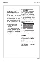
Insulate securely all the
way to the surface on
which the duct connector
is to be attached.
Insulation material
(locally procured)
Duct
Duct connector
①
(accessory)
Aluminum tape
(locally procured)
Outdoor duct
Slope
1/30 or more
Wrap the tape so that air will
not leak.
Duct connection
Installation of indoor duct
Outdoor
Avoid bends and curves in the
ducts to prevent water build-up.
Extreme bend
Multi bend
Signifi cantly reduce the diameter
of the connection duct.
A bend right next to the opening
for duct connection.
Main unit
(Reduce the duct diameter halfway)
Examples of prohibited duct connection
Insulate securely all the way to
the surface on which the duct
connector is to be attached.
Insulation material
(locally procured)
Duct
Duct connector
①
(accessory)
Aluminum tape
(locally procured)
Wrap the tape so that air will
not leak.
Duct connection
Installation of indoor duct
Outdoor
Avoid bends and curves in the
ducts to prevent water build-up.
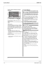
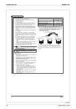
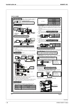
Do not connect the duct to the inside of the duct connector
①
(accessory). This may
cause reduced fan speed, unusual noise, or failure of the fan motor.
Duct connector
①
(accessory)
Duct connector
①
(accessory)
Duct
Duct
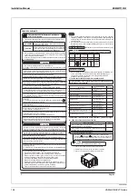
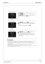
<CAUTION>
Do not connect the duct to the inside of the duct connector
①
(accessory). This may
cause reduced fan speed, unusual noise, or failure of the fan motor.
Duct connector
①
(accessory)
Duct connector
①
(accessory)
Duct
Duct
<CAUTION>
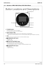
VAM150-1000HV
E
VAM1500-2000HV
E
①
Summary of Contents for VAM Series
Page 2: ......
Page 4: ...EDMMT712101 2 Table of Contents 17 6 Precautions for Design and Installation 181 ...
Page 56: ...Control System EDMMT712101 54 VAM HVE HVLT Series C 3P343420 1E ...
Page 138: ...Installation Manual EDMMT712101 136 VAM HVE HVLT Series 3P607378 3C ...
Page 139: ...EDMMT712101 Installation Manual VAM HVE HVLT Series 137 3P607378 3C ...
Page 141: ...EDMMT712101 Installation Manual VAM HVE HVLT Series 139 C EM20A032 ...
Page 142: ...Installation Manual EDMMT712101 140 VAM HVE HVLT Series C EM20A032 ...
Page 143: ...EDMMT712101 Installation Manual VAM HVE HVLT Series 141 C EM20A032 ...
Page 147: ...EDMMT712101 Details of Optional Accessories VAM HVE HVLT Series 145 3P607378 3C ...
Page 148: ...Details of Optional Accessories EDMMT712101 146 VAM HVE HVLT Series 3P607378 3C ...
Page 149: ...EDMMT712101 Details of Optional Accessories VAM HVE HVLT Series 147 3P607378 3C ...
Page 150: ...Details of Optional Accessories EDMMT712101 148 VAM HVE HVLT Series 3P607378 3C ...
Page 151: ...EDMMT712101 Details of Optional Accessories VAM HVE HVLT Series 149 3P607378 3C ...
Page 152: ...Details of Optional Accessories EDMMT712101 150 VAM HVE HVLT Series 3P607378 3C ...
Page 155: ...EDMMT712101 Details of Optional Accessories VAM HVE HVLT Series 153 4P457318 1D ...
Page 156: ...Details of Optional Accessories EDMMT712101 154 VAM HVE HVLT Series 4P457318 1D ...
Page 157: ...EDMMT712101 Details of Optional Accessories VAM HVE HVLT Series 155 4P457318 1D ...
Page 158: ...Details of Optional Accessories EDMMT712101 156 VAM HVE HVLT Series 4P457318 1D ...
Page 159: ...EDMMT712101 Details of Optional Accessories VAM HVE HVLT Series 157 4P457318 1D ...
Page 184: ......
Page 185: ......
Page 186: ......
Page 187: ......


