


Installation Manual
EDMMT712101
128
VAM-HVE/HVLT Series
3P645058-1
6
English
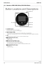
t
Shut off the power before doing any work.
t
All field supplied parts and materials, electric works must
conform to local codes.
t
Use copper wire only.
t
All wiring must be performed by an authorized electrician.
t
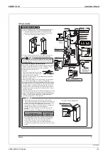
See also the “Electrical Wiring Diagram label” attached to the
electric parts box lid when laying electrical wiring.
t
Wire the remote controller as shown in the electric wiring
diagram label. See the “Remote Controller Installation Manual”
for details on how to install and lay the wiring for the remote
controller.
t
Install a wiring interrupter or ground-fault circuit interrupter for
the power wiring.
t
Make sure the ground resistance is no greater than 100 .
This value can be as high as 500 when using a ground fault
circuit interrupter since the protective ground resistance can be
applied.
t
Do no let the ground wire should come in contact with gas
pipes, water pipes, lighting rods, or telephone ground wires.
t
Gas pipes: gas leaks can cause explosions and fire.
t
Water pipes: cannot be grounded if hard vinyl pipes are
used.
t
Telephone ground and lightning rods: the ground potential
when struck by lightning gets extremely high.
t
Do not turn on the power supply (wiring interrupter or ground-
fault circuit interrupter) until all other work is done.
E
L
E
CTRIC
WIRING
WORK
6
CAUTION
Before
obtaining
access
to
terminal
devices,
all
po
w
er
supply
circuits
must
be
interrupted.
6-1
PR
E
CAUTIONS
WH
E
N
LAYING
POW
E
R
SUPPLY
WIRING
[
PR
E
CAUTION
]
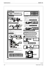
1.
A circuit breaker capable of shutting down power supply to the
entire system must be installed.
2.
A single switch can be used to supply power to units on the
same system. However, branch switches and branch circuit
breakers must be selected carefully.
3.
Fit the power supply wiring of each unit with a switch and fuse
as shown in the drawing.
4.
Be sure to give the electric grounding (earth) connection. Do
not use solid conductor in the wiring of earth terminal.
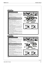
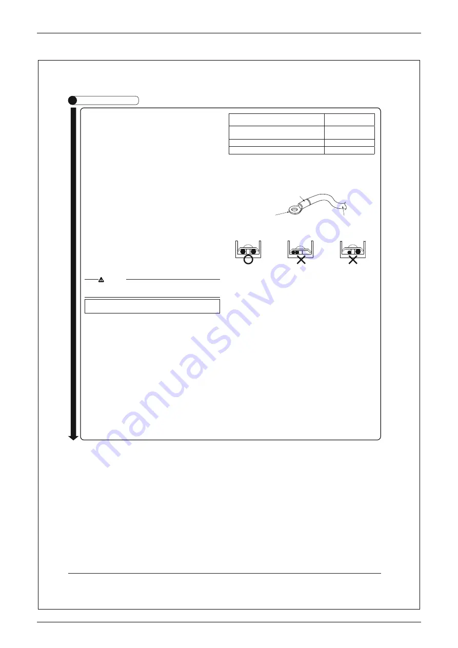
5.
Tightening torque for the terminal screws.
t6TFUIFDPSSFDUTDS
ewdriver for tightening the terminal
screws. If the blade of screwdriver is too small, the head
of the screw might be damaged, and the screw will not be
properly tightened.
t*GUIFUF
rminal screws are tightened too hard, screws might
be damaged.
t3F
fer to the table below for the tightening torque of the
terminal screws.
Tightening torque
(N·m)
Treminal block for remote controller/
Transmission wiring (X2M)
0.79 – 0.97
Power supply terminal block (X1M)
1.18 – 1.44
4
9
.
1
–
4
4
.
1
)
4
M
(
l
a
n
i
m
r
e
t
d
n
u
o
r
G
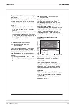
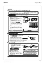
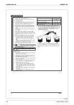
6.
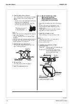
Connect round crimp-style terminals provided with insulation
sleeves to the terminal block for power supply. Be sure to follow the
instructions provided below if the specifi ed terminals cannot be used.
Other
w
ise,
abnormal
heat
may
be
generated
as
a
result
of
the
loosening
of
the
w
ires.
Attach insulation sleeve
Round crimp-style terminal
Electric wire
Connect the wires
evenly.
Do not connect a
wire to the single
side only.
Do not connect wires
different from each
other in diameter.
7.
Do not connect wires of different gauge to the same grounding
terminal. Looseness in the connection may deteriorate protection.
8.
Keep the power supply wiring distant from other wires to prevent
noise.
Summary of Contents for VAM Series
Page 2: ......
Page 4: ...EDMMT712101 2 Table of Contents 17 6 Precautions for Design and Installation 181 ...
Page 56: ...Control System EDMMT712101 54 VAM HVE HVLT Series C 3P343420 1E ...
Page 138: ...Installation Manual EDMMT712101 136 VAM HVE HVLT Series 3P607378 3C ...
Page 139: ...EDMMT712101 Installation Manual VAM HVE HVLT Series 137 3P607378 3C ...
Page 141: ...EDMMT712101 Installation Manual VAM HVE HVLT Series 139 C EM20A032 ...
Page 142: ...Installation Manual EDMMT712101 140 VAM HVE HVLT Series C EM20A032 ...
Page 143: ...EDMMT712101 Installation Manual VAM HVE HVLT Series 141 C EM20A032 ...
Page 147: ...EDMMT712101 Details of Optional Accessories VAM HVE HVLT Series 145 3P607378 3C ...
Page 148: ...Details of Optional Accessories EDMMT712101 146 VAM HVE HVLT Series 3P607378 3C ...
Page 149: ...EDMMT712101 Details of Optional Accessories VAM HVE HVLT Series 147 3P607378 3C ...
Page 150: ...Details of Optional Accessories EDMMT712101 148 VAM HVE HVLT Series 3P607378 3C ...
Page 151: ...EDMMT712101 Details of Optional Accessories VAM HVE HVLT Series 149 3P607378 3C ...
Page 152: ...Details of Optional Accessories EDMMT712101 150 VAM HVE HVLT Series 3P607378 3C ...
Page 155: ...EDMMT712101 Details of Optional Accessories VAM HVE HVLT Series 153 4P457318 1D ...
Page 156: ...Details of Optional Accessories EDMMT712101 154 VAM HVE HVLT Series 4P457318 1D ...
Page 157: ...EDMMT712101 Details of Optional Accessories VAM HVE HVLT Series 155 4P457318 1D ...
Page 158: ...Details of Optional Accessories EDMMT712101 156 VAM HVE HVLT Series 4P457318 1D ...
Page 159: ...EDMMT712101 Details of Optional Accessories VAM HVE HVLT Series 157 4P457318 1D ...
Page 184: ......
Page 185: ......
Page 186: ......
Page 187: ......


