


Installation Manual
EDMMT712101
130
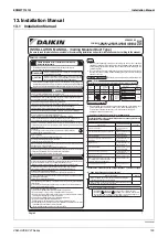
VAM-HVE/HVLT Series
3P645058-1
8
English
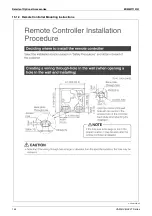
6-2
Wiring
Connection
Method
(1)
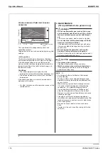
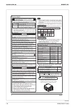
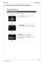
Remove 2 mounting screws of the electrical component box to open it.
(2)
Perform installation of remote controller and power supply wiring.
Fix the power supply wiring, earth wires, and transmission wiring
(signal line and remote controller) securely in place with the clamp
③
(accessory) as shown in the figure on the right.
Mounting screw
Wiring through-hole
Electrical
component box
(3) When closing the electrical component box, make sure that the cover
catches no wire, and then fix it securely with 2 mounting screws.
Form
the
w
iring
orderly
so
that
the
electrical
component
box
can
be
securely
attached.
Electric wires that got pinched or the electrical component box that does not sit properly may
cause electric shock or fire.
WARNING
<
Connecting
po
w
er
supply
w
iring
and
earth
w
ires>
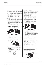
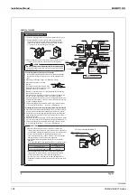
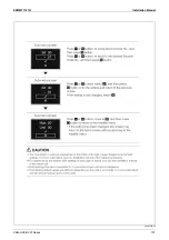
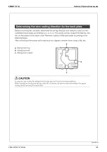
y
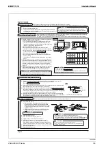
Pass the power supply wiring and the earth wires through the wiring through-
hole (upper) into the electrical component box, as shown in the figure on the
right.
y
Connect the power supply wiring to the terminal block (X1M).
y
Connect the earth wires to the earth
terminals.
Take out the earth wire from the notch of the
cup washer and lay the wire carefully so that
the washer will not catch other wires.
Earth
screw
Cup washer
Spring washer &
plain washer
Notch
Round crimp-style
terminal
Otherwise, the earth wire may not contact sufficiently, and the earthing
effect of the wire may be lost.
Route the wiring so the earth wire and the round crimp-style terminal will
not come off of the sheet metal as shown in the figure on the right.
If the power supply wiring, earth wire, and round crimp-style terminal come
off the sheet metal, they may contact the connector when the electrical box
is closed, resulting in damage.
y
Fix the power supply wiring and earth wires securely to the resin clamps
(2 locations) with the clamp
3
(accessory). (Enlarged view – 1)
<Connecting
remote
controller
w
iring
and
transmission
w
iring
(lo
w
voltage)>
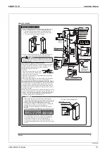
y
See the “Remote Controller Installation Manual” that comes with the remote
controller for details on installation of and wiring for the remote controller.
y
Pass the remote controller wiring and the transmission wiring through the
wiring through-hole (lower) into the electrical component box, as shown in
the figure on the right.
y
Connect the remote controller wiring to [P1/P2] and the transmission wiring
to [F1 / F2] of the terminal block (X1M), respectively. (No polarity: Enlarged view – 2)
y
Fix the power supply wiring and earth wires securely to the resin clamps
(1 locations) with the clamp
③
(accessory). (Enlarged view – 1)
Resin clamp
Enlarged view - 1
Enlarged view - 3
Enlarged view - 2
Power supply
wires
Earth wire
Wiring through-hole
Clamp
③
(accessory)
Clamp
③
(accessory)
(for power supply wiring and earth wires)
Clamp
③
(accessory)
(for power supply wiring and earth wires)
Cup washer
Clamp
③
(accessory)
Notch
Sheet metal
Round crimp-style
terminal
Wiring
Resin clamp
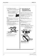
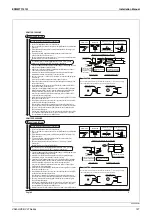
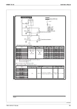
Terminal block (X1M)
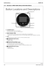
Do not clamp low voltage wires together with high voltage wires.
Otherwise, electrical noise (external noise) could cause malfunction or failure.
Factory default setting
P2 P1 F1 F2
J1 J2 J3 JC
NOR.
SS1
H
M
Terminal block (X2M) (for external input)
Terminal block (X1M)
(for remote controller / transmission wiring)
Terminal block (X3M)
(for combined operation with external damper/operation indication)
Earth terminal (M4 screw + spring plain cup washer)
Electrical component box
Printed circuit board
Never connect the power supply
wiring to the terminal block.
Remote
controller
Central
Connect the remote controller and transmission wiring.
Do not change the switch settings. SS1 is the switch
setting for remote control.
Do not change
The unit does not operate if the setting is changed.
Fix the remote controller wiring and transmission wiring securely with a clamping sheet.
Resin coated section
Edge of sheet metal
Wind the clamping sheet only
around the resin-coated section so
that the wiring will not contact the
edge of the sheet metal.
No-voltage
external input
<Prohibition>
<Prohibition>
<CAUTION>
Connect transmission wirings securely
using round crimp-style terminals.
Do not allow it to come off of the sheet metal
NOR.
SS1
H
M
X1M
X2M
X3M
Spring washer &
plain washer
Earth
screw
Earth wire and round crimp-style terminal
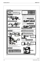
y
Make sure that all wiring is securely connected to the respective
terminal, using the specified wires, and the sheath section is fixed with a
provided clamp, ensuring that external forces do not act on the terminal.
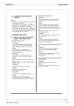
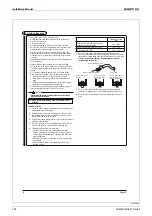
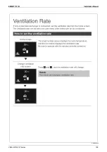
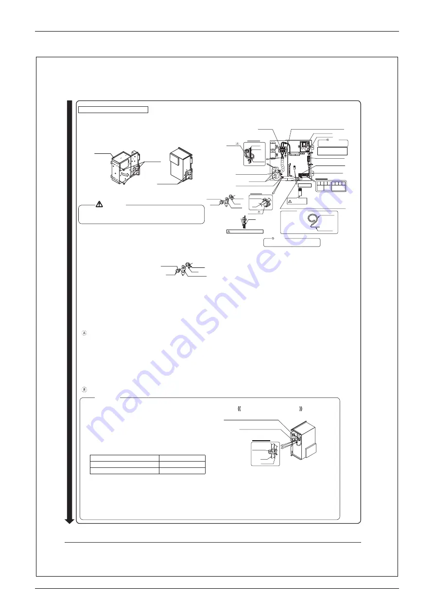
In case of reverse installation
Enlarged view – 4
Clamp
③
(accessory)
(for remote controller wiring and transmission wiring)
Clamp
③
(accessory)
(for power supply wiring and earth wires)
Clamp
③
(accessory)
Wiring
Push mount
y
Use the correct screwdriver for tightening the terminal screws.
If the screwdriver’s blade is too small, the head of the screw might be
damaged, and the screw will not be properly tightened.
y
If the terminal screws are tightened too hard, the screws might be
damaged.
Refer to the table below for the tightening torque of the terminal screws.
Tightening torque (N·m)
Earth terminal (M4)
1.69±0.25
Terminal block (X1M, X2M, X3M) (M3.5)
0.8±0.08
y
When installing the unit upside down, fix the external wiring (power
supply wiring, earth wires, remote control wiring, and transmission
wiring) to the push mounts (1 location each) with the clamp
③
(accessory) as shown in the figure on the right. (Enlarged view – 4)
Condensation water may enter the electrical component box and cause
a failure.
<CAUTION>
VAM150-1000HV
E
Summary of Contents for VAM Series
Page 2: ......
Page 4: ...EDMMT712101 2 Table of Contents 17 6 Precautions for Design and Installation 181 ...
Page 56: ...Control System EDMMT712101 54 VAM HVE HVLT Series C 3P343420 1E ...
Page 138: ...Installation Manual EDMMT712101 136 VAM HVE HVLT Series 3P607378 3C ...
Page 139: ...EDMMT712101 Installation Manual VAM HVE HVLT Series 137 3P607378 3C ...
Page 141: ...EDMMT712101 Installation Manual VAM HVE HVLT Series 139 C EM20A032 ...
Page 142: ...Installation Manual EDMMT712101 140 VAM HVE HVLT Series C EM20A032 ...
Page 143: ...EDMMT712101 Installation Manual VAM HVE HVLT Series 141 C EM20A032 ...
Page 147: ...EDMMT712101 Details of Optional Accessories VAM HVE HVLT Series 145 3P607378 3C ...
Page 148: ...Details of Optional Accessories EDMMT712101 146 VAM HVE HVLT Series 3P607378 3C ...
Page 149: ...EDMMT712101 Details of Optional Accessories VAM HVE HVLT Series 147 3P607378 3C ...
Page 150: ...Details of Optional Accessories EDMMT712101 148 VAM HVE HVLT Series 3P607378 3C ...
Page 151: ...EDMMT712101 Details of Optional Accessories VAM HVE HVLT Series 149 3P607378 3C ...
Page 152: ...Details of Optional Accessories EDMMT712101 150 VAM HVE HVLT Series 3P607378 3C ...
Page 155: ...EDMMT712101 Details of Optional Accessories VAM HVE HVLT Series 153 4P457318 1D ...
Page 156: ...Details of Optional Accessories EDMMT712101 154 VAM HVE HVLT Series 4P457318 1D ...
Page 157: ...EDMMT712101 Details of Optional Accessories VAM HVE HVLT Series 155 4P457318 1D ...
Page 158: ...Details of Optional Accessories EDMMT712101 156 VAM HVE HVLT Series 4P457318 1D ...
Page 159: ...EDMMT712101 Details of Optional Accessories VAM HVE HVLT Series 157 4P457318 1D ...
Page 184: ......
Page 185: ......
Page 186: ......
Page 187: ......


