


Installation Manual
EDMMT712101
134
VAM-HVE/HVLT Series
3P645058-1
12
English
FI
E
LD
S
E
TTING
AND
T
E
ST
RUN
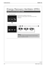
7
7-1
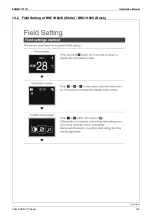
Field
Settings
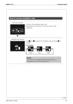
(1) Make sure the electrical component box is closed before turning on the power.
(2) Depending on the type of installation, make the field settings from the remote controller following the “Field Settings” section of the installation manual which came with the remote controller.
y
When a change is made to the settings of [Filter contamination setting], [Night time free cooling operation starting time], or [24-hour ventilation setting], provide your customer the information
described in the Remarks of the table below.
y
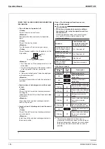
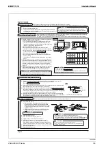
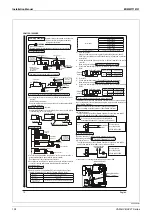
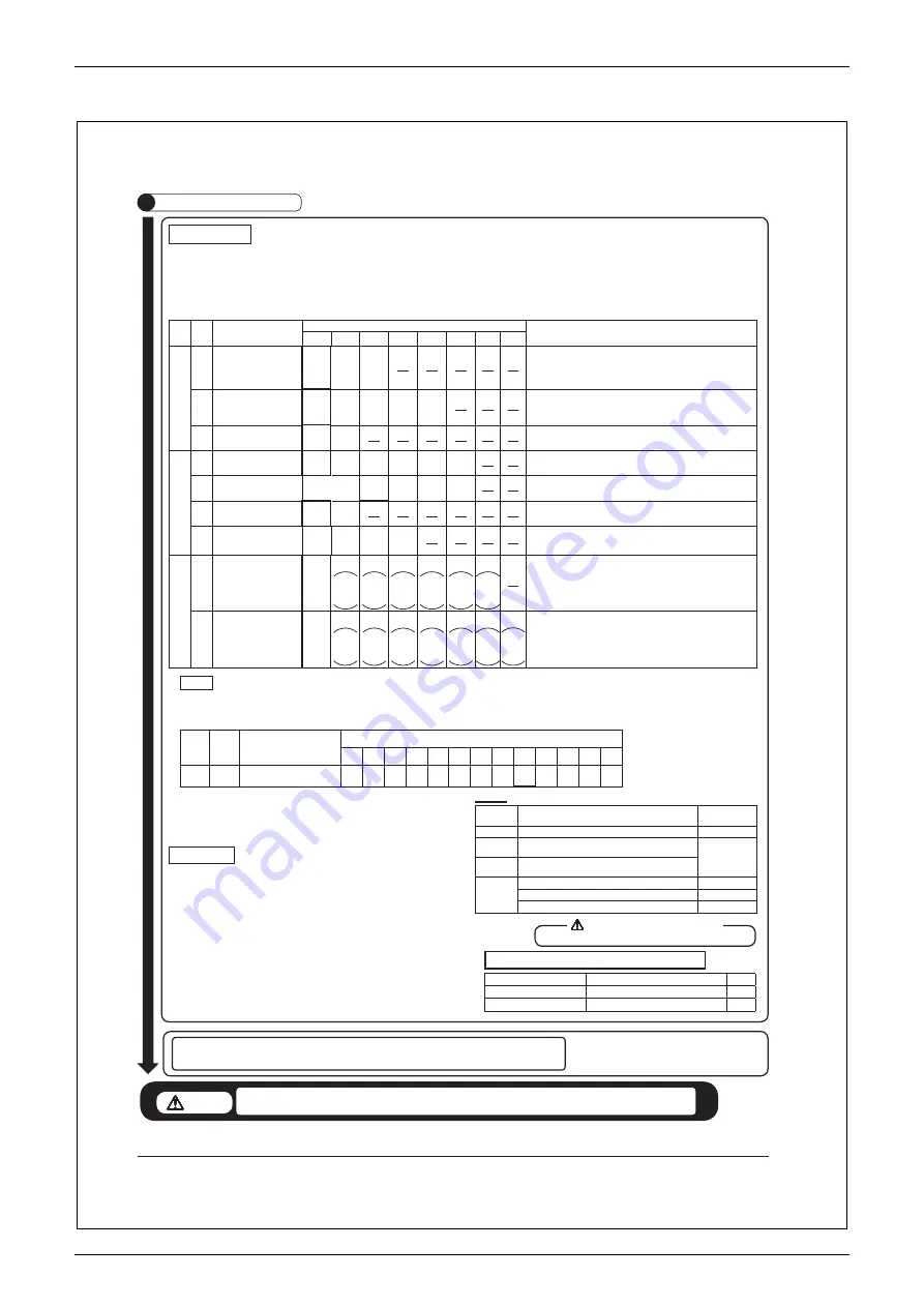
Setting is made by changing the three numbers: “mode number”, “setting switch number”, and “setting position number”.
Descriptions of settings and setting numbers (For other settings, refer to the general catalog.)
Mode
No.
Setting
s
w
itch
No.
Setting
descriptions
Setting
position
No.
Remarks
01
02
03
04
05
06
07
08
17
(27)
0
Fresh-up
(Setting of more supply air/more
exhaust air)
Accumulated
2500 hours
Accumulated
1250 hours
No
accumulation
The factory setting for the fi lter sign display time is 2500 hours (equivalent to 1 year). However, if the unit is installed
in a location subjected to dust and particles, the display time can be shortened to allow the fi lter to be cleaned more
frequently.
If the setting position “03” is selected, the fi lter sign will not be displayed. However, advise the customer that the fi lter
needs to be cleaned regularly to prevent clogging.
1
Nighttime free cooling operation
starting time (after the operation stops)
OFF
ON /
2 hours later
ON /
4 hours later
ON /
6 hours later
ON /
8 hours later
The factory default setting for nighttime free cleaning operation is “OFF”. However, nighttime free cleaning operation
can be set to “ON” by selecting one of the setting position numbers “02” to “05”.
During night nighttime free cleaning operation, the operation indicator lamp on the remote control is off. If the nighttime
free cleaning setting is set to “ON”, please explain this to your customer.
4
Initial setting for ventilation fan
Normal
Ultra high
The factory default setting is the setting position number “01” (the unit operates at a “high” notch when the ventilation
rate displayed on the remote control is “high”). By selecting the setting position number “02”, the unit operates at the
“ultra-high” notch when the ventilation rate displayed on the remote control is “high”.
18
(28)
0
External input setting (J2-JC)
Last command
Priority on
external input
Priority on
operation
Forced OFF
Sync with fan
Ú
24-hour
ventilation
ON/OFF
Selecting the setting position number “04” allows forced OFF by an external input.
Selecting the setting position number “06” cancels 24-hour ventilation operation by an external input.
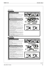
3
Main unit X3M
External contact output changeover
(X1-X2)
Humidifi cation operation output
Fan operation
(Damper output)
Abnormal
output
Filter sign
Output
7
Fresh-up
(Setting of more supply air/more
exhaust air)
Supply air
Exhaust air
The factory default setting is the setting position number “01”: “Supply” Fresh-Up.
Exhaust” Fresh-Up can be set by selecting the setting position number “02”.
11
Main unit X3M
External contact output changeover
(X3-X4)
Fan operation
(Damper output)
Abnormal
output
Filter sign
output
Operation
output
19
(29)
1
Intermittent low tap operation setting
NO
Ventilation
rate 1/15
Fan OFF for 28
minutes
Fan ON for 2
minutes
Ventilation
rate 1/10
Fan OFF for 27
minutes
Fan ON for 3
minutes
Ventilation
rate1/6
Fan OFF for 25
minutes
Fan ON for 5
minutes
Ventilation
rate 1/4
Fan OFF for 22.5
minutes
Fan ON for 7.5
minutes
Ventilation
rate 1/3
Fan OFF for 20
minutes
Fan ON for 10
minutes
Ventilation
rate 1/2
Fan OFF for 15
minutes
Fan ON for 15
minutes
The factory default setting for intermittent low tap operation setting is “OFF”.
The intermittent low tap operation setting can be changed to “ON” by selecting a setting position number.
4
24-hour ventilation setting
NO
Ventilation
rate 1/15
Fan OFF for 28
minutes
Fan ON for 2
minutes
Ventilation
rate 1/10
Fan OFF for 27
minutes
Fan ON for 3
minutes
Ventilation
rate 1/6
Fan OFF for 25
minutes
Fan ON for 5
minutes
Ventilation
rate 1/4
Fan OFF for
22.5 minutes
Fan ON for 7.5
minutes
Ventilation
rate 1/3
Fan OFF for 20
minutes
Fan ON for 10
minutes
Ventilation
rate 1/2
Fan OFF for
15 minute
Fan ON for 15
minutes
Ventilation
rate 1/1
Continuous
opera
The factory default setting for 24-hour ventilation operation setting is “OFF”. 24-hour ventilation operation can be set to
“ON” by selecting one of the setting position numbers “02” – “08”.
During 24-hour ventilation operation, the operation indicator lamp on the remote control is off.
If the 24-hour ventilation setting is set to “ON”, please explain this to your customer.
Disconnect the power supply before changing the wiring or making switch settings.
CAUTION
E
L
E
CTRIC
SHOCK
RISK
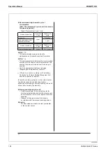
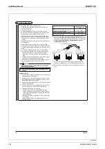
Table
1
Remote controller
display
n
e
k
at
e
b
ot
s
e
r
u
s
a
e
M
kr
o
w
g
ni
ri
w
r
o
n
oi
ta
ll
at
s
ni
n
i
m
el
b
o
r
P
61
t
Error in supply voltage “220-240V”
t
Supply voltage
U5
t
Incorrect setting of “MAIN/SUB” remote controller (two MAIN remote
controllers are connected)
t
Correct
U8
t
Incorrect setting of “MAIN/SUB” remote controller (two SUB remote controllers
are connected)
No display
t
Power supply construction work is not done for the total heat exchanger unit
t
Reset
t
Power of the total heat exchanger unit is not turned on
t
Turn on the power
t
Wrong remote controller wiring or disconnected wires
t
Correct the wiring
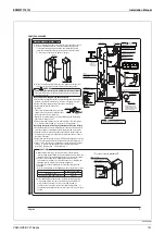
Items to be checked
If not properly done, what is likely to occur
Check
Have you performed a test run
The unit may not operate
Was air taken into each intake?
Ventilation rate is insuffi cient, or noise may occur
7-3
Items
to
be
checked
after
completion
of
test
run
7-2
Test
Run
y
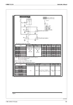
Make sure that all electric wiring works and duct connections have been completed.
(In particular, if a closing damper is installed in the middle of the duct, make sure that it is open.)
y
Make sure the electrical component box of the unit is closed before turning on the power.
y
Perform a test run following the operation manual and make sure that the unit operates properly.
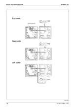
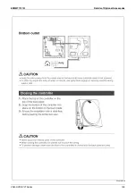
Check the airflow from each outlet and intake, and if the airflow appears weak, check if the fan is rotating.
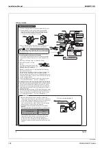
“Measures in the event of abnormal completion”
y
Blinking operation indicator lamp on the remote controller indicates an error. Confirm the error code on the
LCD and check for errors/problems.
Error codes and error descriptions are described in the “Operation Manual” provided.
y
In particular, if the display shows any of the conditions listed in Table 1, it may be due to faulty installation
or wiring work, or the power may not be turned on.
y
The factory default setting position is displayed in the frame.
y
The settings are applied to the entire group, but if the mode number inside the parentheses is
selected, the setting can be applied to individual units.
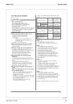
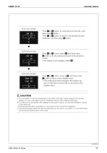
(3) When selecting the single nighttime free cooling operation, make the field setting as follows:
Units
Setting
s
w
itch
No.
Setting
descriptions
Setting
position
No.
01
02
03
04
05
06
07
08
09
10
11
12
13
17
(27)
7
Target temperature for single
nighttime free cooling
18°C 19°C 20°C 21°C 22°C 23°C 24°C 25°C 26°C 27°C 28°C 29°C 30°C
y
The factory default setting for target temperature for single nighttime free cooling is “26°C”. Target
temperature for single nighttime free cooling can be changed by selecting one of the setting
position numbers.
y
Refer to engineering data for details on field settings.
y
Before handing over the unit to the customer after the test run, make sure that the electrical component box, heat exchange element, and air
filter are installed in their proper positions and that the maintenance cover and electrical component box are attached.
CAUTION
y
If an error code other than those in Table 1 is displayed, refer to engineering data or operation manual.
Fix the problem and perform a test run again.
Summary of Contents for VAM Series
Page 2: ......
Page 4: ...EDMMT712101 2 Table of Contents 17 6 Precautions for Design and Installation 181 ...
Page 56: ...Control System EDMMT712101 54 VAM HVE HVLT Series C 3P343420 1E ...
Page 138: ...Installation Manual EDMMT712101 136 VAM HVE HVLT Series 3P607378 3C ...
Page 139: ...EDMMT712101 Installation Manual VAM HVE HVLT Series 137 3P607378 3C ...
Page 141: ...EDMMT712101 Installation Manual VAM HVE HVLT Series 139 C EM20A032 ...
Page 142: ...Installation Manual EDMMT712101 140 VAM HVE HVLT Series C EM20A032 ...
Page 143: ...EDMMT712101 Installation Manual VAM HVE HVLT Series 141 C EM20A032 ...
Page 147: ...EDMMT712101 Details of Optional Accessories VAM HVE HVLT Series 145 3P607378 3C ...
Page 148: ...Details of Optional Accessories EDMMT712101 146 VAM HVE HVLT Series 3P607378 3C ...
Page 149: ...EDMMT712101 Details of Optional Accessories VAM HVE HVLT Series 147 3P607378 3C ...
Page 150: ...Details of Optional Accessories EDMMT712101 148 VAM HVE HVLT Series 3P607378 3C ...
Page 151: ...EDMMT712101 Details of Optional Accessories VAM HVE HVLT Series 149 3P607378 3C ...
Page 152: ...Details of Optional Accessories EDMMT712101 150 VAM HVE HVLT Series 3P607378 3C ...
Page 155: ...EDMMT712101 Details of Optional Accessories VAM HVE HVLT Series 153 4P457318 1D ...
Page 156: ...Details of Optional Accessories EDMMT712101 154 VAM HVE HVLT Series 4P457318 1D ...
Page 157: ...EDMMT712101 Details of Optional Accessories VAM HVE HVLT Series 155 4P457318 1D ...
Page 158: ...Details of Optional Accessories EDMMT712101 156 VAM HVE HVLT Series 4P457318 1D ...
Page 159: ...EDMMT712101 Details of Optional Accessories VAM HVE HVLT Series 157 4P457318 1D ...
Page 184: ......
Page 185: ......
Page 186: ......
Page 187: ......


