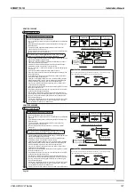
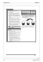
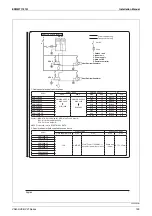
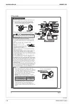
background image

Installation Manual

EDMMT712101

136

VAM-HVE/HVLT Series

3P607378-3C

Summary of Contents for VAM Series

Page 1: ...VAM 150HVE HVLT VAM 250HVE HVLT VAM 350HVE HVLT VAM 500HVE HVLT VAM 650HVE HVLT VAM 800HVE HVLT VAM1000HVE HVLT VAM1500HVE HVLT VAM2000HVE HVLT 50 60 Hz EDMMT712101 Heat Reclaim Ventilator VAM Series ...

Page 2: ......

Page 3: ... 142 14 1 Optional Accessories 142 15 Details of Optional Accessories 143 15 1 BRC1H62W White BRC1H62K Black Remote Controller 143 15 2 BRC1E63 Remote Controller 151 15 3 KRP1C18 Printed Circuit Board Adaptor for Wiring 158 15 4 KRP1C18A90 Installation Box for Adaptor Printed Circuit Board 159 15 5 KDDM24B100 Silencer 162 15 6 KAF241J25M KAF241J50M KAF241J65M KAF241K100M Air Filter for Replacement...

Page 4: ...EDMMT712101 2 Table of Contents 17 6 Precautions for Design and Installation 181 ...

Page 5: ...s due to unconditioned outside air Good quality air for every day This unit recovers heat energy lost through ventilation and curbs room temperature changes caused by ventilation thereby conserving energy and reducing the load on the air conditioning system Total heat exchange ventilation Molecule of water Miscellaneous gas CO2 molecule etc Sheet structure Outdoor Indoor Furthermore miscellaneous ...

Page 6: ... in through windows and doors the indoor air is kept under negative pressure and discharged Dust Doorway SA EA EA SA hallway Positive pressure Negative pressure A i r f l o w C o n t r o l F r e s h u p O p e r a t i o n Class 1 Ventilation Class 2 Ventilation Class 3 Ventilation Both supply air and exhaust air are controlled by mechanical ventilation in order to achieve stable ventilation when re...

Page 7: ...tration During increase in CO2 level in the room ventilation air volume will be increased to have higher air exchange in order to reduce the CO2 level in room Human occupancy is reflected as CO2 concentration 13 Person 4 Person 4 Person Ventilation ON Ventilation ON Ventilation OFF Number of people in the room Number of people in the room Number of people in the room Even if the number of people d...

Page 8: ... units During 24 hours ventilation mode is turned on the normal operation mode is changed to 24 hours ventilation mode Once the absence is detected and stopped the operation will not be performed automatically again Pre cooling Pre heating control Delay timer settings can be adjusted Total heat exchanger Operation OFF Air Supply Exhaust Operation OFF Air conditioner Air Supply Exhaust Operation ON...

Page 9: ...utdoor air temperature sensor Air supply fan Air exhaust fan Supply air Return air Outdoor air intake Exhaust air When connected to air conditioners operation of heat reclaim ventilator is controlled according to the set temperature outside air temperature and room temperature When using only ventilation unit operation of heat reclaim ventilator is controlled according to the set temperature on re...

Page 10: ...ide air is coming in when the entrance door is opened The restaurant has negative room pressure due to insufficient supply air When the entrance door is opened outside air enters into the restaurant bringing warm air and pollutants Negative pressure kitchen restroom Entrance Dining area Negative pressure resolved kitchen restroom Dining area Entrance Lack of airflow Shop Shop Problem Countermeasur...

Page 11: ...ls indicates energy savings Airflow rate up Airflow rate up Airflow rate down Airflow rate down If airflow rate were constant Automatic Ventilation Mode Swithching Bypass control with Humidity sensor The ventilation unit detects room temperature and outside air temperature then automatically switches to suitable ventilation mode to provide higher energy saving By installing humidity sensor optiona...

Page 12: ...s 1 1 Nomenclature V A M H VE 500 Ventilation Air Mounted type Airflow rate m3 h Major design category Design category for EC application Power supply VE 1 phase 220 240 220 V 50 60 Hz VL 1 phase 220 V 60 Hz Standard symbol T Taiwan Blank General countries ...

Page 13: ...t fan Duct connector Damper Air supply fan Air filter Electrical component box Heat exchange element EA Exhaust air Exhaust air to outdoor SA Supply air Feed air to room RA Return air Exhaust air from room OA Outdoor air Fresh air from outdoor Exhaust fan Connection chamber Damper Air supply fan Air filter Electrical component box Heat exchange elements EA Exhaust air Exhaust air to outdoor SA Sup...

Page 14: ... for cleaning the filter 8 Advantage to IEQ Indoor Environment Quality Note 5 6 can be set at the initial setting only Installation Examples Type Interlocked operation with air conditioner Heat Reclaim Ventilator VAM series independent operation Structure Features Simultaneous operation with air conditioner s remote controller is available Operation Stop Ventilation mode changeover Timer mode star...

Page 15: ...the air conditioner by the following control Before the working hour the room air is clean Therefore the startup of Heat Reclaim Ventilator VAM series can be delayed By heat recovery operation Exhaust Air Exhaust Air Outdoor Air Heat Exchanger Element Heat Recovery Return Air Supply Air By setting to automatic ventilation mode Operation Sensor of ventilation Decision of mode Which is more energy e...

Page 16: ...rs from rooms in a nursing home Application Offices etc Hospitals Nursing homes etc Example Model name Height mm VAM150HVE HVLT 278 VAM250HVE HVLT 278 VAM350HVE HVLT 306 VAM500HVE HVLT 338 VAM650HVE HVLT 338 VAM800HVE HVLT 387 VAM1000HVE HVLT 387 VAM1500HVE HVLT 785 VAM2000HVE HVLT 785 Upside down installation is available It allows the common use of the inspection hole and reduces the space and i...

Page 17: ...t such as dew condensation and freezing The unit does not ventilate But to detect the elevation of the outdoor air temperature the unit operates for 5 minutes per hour The control by the external damper local purchase is available When the unit is not operating the unit prevents the cool outdoor air from invading The contact signal is received from the connector X3M to the external damper Therefor...

Page 18: ...determined from Table 1 The above equation conforms to ASHRAE Standard 62 1 2019 Notes 1 Equation 1 accounts for people related sources and area related sources independently in the determination of the outdoor air rate required at the breathing zone The use of Equation 1 in the context of this standard does not necessarily imply that simple addition of outdoor airflow rates for different sources ...

Page 19: ...r requirements for buildings containing ETS areas and ETS free areas 3 Air density Volumetric airflow rates are based on an air density of 0 075 lbda ft3 1 2 kgda m3 which corresponds to dry air at a barometric pressure of 1 atm 101 3 kPa and an air temperature of 70 F 21 C Rates may be adjusted for actual density but such adjustment is not required for compliance with this standard 4 Default occu...

Page 20: ...free areas 3 Air density Volumetric airflow rates are based on an air density of 0 075 lbda ft3 1 2 kgda m3 which corresponds to dry air at a barometric pressure of 1 atm 101 3 kPa and an air temperature of 70 F 21 C Rates may be adjusted for actual density but such adjustment is not required for compliance with this standard 4 Default occupant density The default occupant density shall be used wh...

Page 21: ...ic airflow rates are based on an air density of 0 075 lbda ft3 1 2 kgda m3 which corresponds to dry air at a barometric pressure of 1 atm 101 3 kPa and an air temperature of 70 F 21 C Rates may be adjusted for actual density but such adjustment is not required for compliance with this standard 4 Default occupant density The default occupant density shall be used when actual occupant density is not...

Page 22: ...0 075 lbda ft3 1 2 kgda m3 which corresponds to dry air at a barometric pressure of 1 atm 101 3 kPa and an air temperature of 70 F 21 C Rates may be adjusted for actual density but such adjustment is not required for compliance with this standard 4 Default occupant density The default occupant density shall be used when actual occupant density is not known 5 Default combined outdoor air rate per p...

Page 23: ...ntilation rate L s Afloor dwelling unit floor area m Nbr number of bedrooms not to be less than 1 The above equation i and ii conforms to ASHRAE Standard 62 2 2019 Table i I P Ventilation Air Requirements cfm Table ii SI Ventilation Air Requirements L s Floor Area ft Bedrooms 1 2 3 4 5 500 30 38 45 53 60 501 to 1000 45 53 60 68 75 1001 to 1500 60 68 75 83 90 1501 to 2000 75 83 90 98 105 2001 to 25...

Page 24: ...ing a remote controller During intermediate periods independent operation of Heat Reclaim Ventilator Unit is also possible with a remote controller Independent operation is not available in the case of duct direct connection with air conditioners Indoor unit Heat Reclaim Ventilator Unit Heat Reclaim Ventilator Unit Remote controller Maximum total number of units 16 units 〇 〇 〇 〇 〇 〇 〇 Centralized ...

Page 25: ... to the same terminal If there are three or more transmission cables use a relay terminal block locally procured The illustrations in this Engineering Data Book are based on the multidrop network which does not require relay terminal blocks Switches and Terminals of Main Unit Control Board Introduction to Switches Switch Functions NOR H M Be sure to set this switch to NOR SS1 is a special use sele...

Page 26: ... to pages 42 44 for switching to other functions Field Settings of Centralized Zone Interlock Setting Using Remote Controller When Heat Reclaim Ventilator Unit is connected to the centralized transmission line between F1 and F2 terminals it is necessary to consider changing the default field setting of centralized zone interlock setting using the remote controller Combination with centralized contr...

Page 27: ...ow Adapter for wiring output changeover selection Between X3 X4 12 9 Humidification output ordinary humidification Abnormal output Fan operation Ultra high High Low Fan operation Ultra high High Fan operation Ultra high Fan operation Ultra high High Low Fan operation Ultra high High Low Adapter for wiring output changeover selection Between X1 X2 12 9 Normal operation Normal operation Normal operati...

Page 28: ...ed with air conditioner Priority on operation The unit operates when either the remote controller for the air conditioner or external input is set to start when interlocked with air conditioner This setting can be made only during interlock with air conditioner Forced OFF The unit stops operation at the occurrence of a contact input by external input No automatic recovery 3 This setting can be mad...

Page 29: ...g Auto Heat exchanger Bypass Ventilation rate switching High Low Timer setting ON OFF Filter sign display Abnormal digital display Number of units controlled Wiring length Control one Heat Reclaim Ventilator Unit with one remote controller Total remote controller wiring length Up to 500m Control one Heat Reclaim Ventilator Unit with two remote controllers Total remote controller wiring length Up t...

Page 30: ...connection is provided to the centralized transmission line Adapter can also be connected to the air conditioner Functions Energy saving interlocked operation is performed by operating the remote controller for indoor unit of commercial multi air conditioners building multi SkyAir Ventilation mode and rate can be switched for BRC1H62 BRC1E63 Other settings are made in the field setting mode Energy ...

Page 31: ...edule timer It is possible to set batch start stop twice a day on a weekly basis With 48 hour backup time for each occurrence of power failure Wiring adapter for electrical appendices Simultaneous batch start stop is possible by external input Remote controller Interlocked operation with air conditioner can be performed Independent operation of Heat Reclaim Ventilator Unit can be performed Individ...

Page 32: ...e controller The wiring for the main unit to remote controller needs to be locally procured Make the field setting for ventilation rate ultra high by using a remote controller Example of control wiring P1P2 P1P2 Heat Reclaim Ventilator Unit Remote controller Note The maximum length of remote controller cord is up to 500m Switch number that needs to be changed for the system NIL Remans at the factor...

Page 33: ...Reclaim Ventilator Unit Remote controller Note The maximum length of remote controller cord is up to 500m Remote controller Main Sub Group control Purpose Function Controls multiple Heat Reclaim Ventilator Units up to 16 units simultaneously on a large floor All operations and individual setting functions of the remote controller can be collectively performed Even in the event where unusual display...

Page 34: ... the group control wiring of commercial multi air conditioners multi for buildings SkyAir Add a remote controller to perform control by 2 remote controllers Control by 2 remote controllers cannot also be performed using BRC1H62 and BRC1E63 Perform field settings to Heat Reclaim Ventilator Unit in the field setting mode number 17 27 19 29 See pages 25 26 for contents When performing independent opera...

Page 35: ...t operation of Heat Reclaim Ventilator Unit to prevent dust from falling from the air filter of the air conditioner When operating Heat Reclaim Ventilator Unit during intermediate periods set the operation mode of the air conditioner to fan mode and operate it a low fan speed 24 hour operation setting and intermittent weak notch operation are not available for duct direct connection system Be sure ...

Page 36: ...te controller needs be connected to Heat Reclaim Ventilator Unit as well Connect a remote controller to P1 and P2 terminals to make the setting When the units are to be used without remote controller remove the remote controller connected after the installation Example of control wiring F1F2 F1F2 X11A F1F2 BC W1 P1 P2 P1 P2 P1 P2 P1 P2 P1 P2 P1 P2 W2 W3 W4 B2 B1 KRP2A62 To be incorporated into Hea...

Page 37: ... with air conditioner To perform energy saving interlocked control consider adopting one of the following systems 1 group interlocking control system See page 33 In this case do not connect centralized transmission line of Heat Reclaim Ventilator Unit Zone interlock system using central remote controller See page 36 Follows the operation codes of the Unified ON OFF controller including prohibition ...

Page 38: ...F can be made Zone interlock setting is not required for Zone 2 This means that the factory default settings are maintained When operation is performed without remote controller the unit can be operated only from central remote controller Example of control wiring P1P2 P1P2 P1P2 P1P2 P1P2 P1P2 P1P2 P1P2 F1F2 F1F2 F1F2 F1F2 Power supply Heat Reclaim Ventilator Unit Indoor unit Remote controller Rem...

Page 39: ...ol wiring Heat Reclaim Ventilator Unit P1 P2 P1 P2 P1 P2 F1 F2 F1 F2 Centralized transmission line To centralized control equipment Indoor unit Remote controller Examples of Wiring and System Design Error A remote controller needs to be connected to remote controller transmission line When a remote controller transmission line is connected be sure to connect a remote controller on the transmission...

Page 40: ...nsects may enter into indoor spaces if the power is turned off while the ventilation mode is set to Bypass mode If a remote controller is connected ordinary operations can be performed after the power is turned on Example of control wiring P1 P2 P1 P2 Remote controller Heat Reclaim Ventilator Unit Switch number that needs to be changed for the system Field settings using remote controller is requi...

Page 41: ...ing output changeover setting X1 2 Remains at the factory default setting Extraction of error indication Adapter for wiring output changeover setting X3 4 18 28 9 02 When using both operating indication and error indication together please set to 18 28 9 02 Mode No Setting switch No Setting position 01 02 03 04 05 06 07 Adapter for wiring Output changeover selection X3 4 terminals 18 28 9 Humidific...

Page 42: ...ch number that needs to be changed for the system Field settings using remote controller is required Field settings using remote controller Mode No Setting switch No Setting position 01 02 03 04 05 06 Main unit terminal block X3M Output A changeover selection X1 2 terminals 18 28 3 Damper output Abnormal output Filter sign Main unit terminal block X3M Output B changeover selection X3 4 terminals 1...

Page 43: ...an Remote controller External input Fan operation Airflow rate Fresh up Between J1 JC Fresh up Supply mode Fresh up Exhaust mode SA EA SA EA Normal Low OFF OPEN Low Low Low Low ON Short circuit High Low Low High High OFF OPEN High High High High ON Short circuit Ultra high High High Ultra high Ultra high Low OFF OPEN Low Low Low Low ON Short circuit High Low Low High High OFF OPEN Ultra high Ultra ...

Page 44: ...ut contact Fan operation Operation lamp Behaviors 01 Fresh up a Operation ON Fresh up operation 02 Batch alarm a Operation ON Displays error code 60 03 Batch error a Stop Blinking Displays error code 60 04 Forced OFF b Stop OFF No automatic recovery 05 Fan forced OFF b Stop ON Performs automatic recovery 06 More airflow a Operation ON Airflow rate increases Low High Ultra high Example of control wir...

Page 45: ...n 01 02 03 04 External input setting between J2 JC 18 28 0 Last command Priority on external input Priority on operation Forced OFF Factory default setting Details of external input setting Setting position Control details 01 Last command Only during independent operation of Heat Reclaim Ventilator Unit External input is not allowed when interlocked with air conditioner 02 Priority on external inp...

Page 46: ...er Example of control wiring J1 J3 SS1 J2 JC P1 P2 Heat Reclaim Ventilator Unit Contact on site Contact on site Functions External contact Operation External contact specifications Ventilation rate changeover J1 JC Open Ultra high High Non voltage normally open contact Microcurrent contact Minimum applicable load DC12V 1mA or below Closed Low Start Stop J2 JC Open Stop Closed Operation Ventilation ...

Page 47: ...lectric damper locally procured Main unit control PCB Note Be sure to insulate the electric damper installed on the outdoor duct locally procured to prevent condensation Example of control wiring A harness to damper is connected to X1 X2 terminals on the printed circuit board X1 X3M X2 X3 X4 To electric damper Heat Reclaim Ventilator Unit Contact capacity NO VOLTAGE A CONTACT 240 VA or below Switc...

Page 48: ...n operation as it involves a delay Indoor unit is necessary within the same zone Delay time can be selected from 30 45 60 minutes by field setting If this delay time is insufficient it can be further extended by 30 60 90 minutes only for pre heating operation N N N Y Y Y Operation command Set time 30 45 60 minutes Only during heating 30 60 90 minutes Time count Operation standby Operation start Pres...

Page 49: ...erature the operation starts and when the indoor temperature reaches the temperature setting of the air conditioner the operation stops Example of control wiring F1 F2 P1P2 P1P2 P1P2 Heat Reclaim Ventilator Unit Indoor unit Note The maximum length of remote controller cord is up to 500m Remote controller N N N N Y Y Y Y N Y Air conditioner Operation stops Start condition of nighttime free cooling ...

Page 50: ...operation starts and when the indoor temperature reaches the temperature setting of the air conditioner the operation stops Example of control wiring P1P2 P1P2 Heat Reclaim Ventilator Unit Remote controller N N N N Y Y Y Y N Y Heat Reclaim Ventilator Unit Operation Stop Start condition of nighttime free cooling Stop condition of nighttime free cooling Nighttime free cooling ON OFF Start time setti...

Page 51: ...oller 9 hours 12 hours 20 hours 13 hours Operation Stop Stop Operation High Low Fan control and remote controller display during 24 hour ventilation Note 1 The operation indicator on the remote controller is OFF during the 24 hour ventilation operation However external output can be performed by changing the field settings and by using an adapter printed circuit board 2 If the Auto Display Off func...

Page 52: ...ut 18 28 0 06 Intermittent low fan speed Intermittent low notch operation Purpose Functions When low fan operation is performed by remote controller the operation can be selected from low notch continuous operation and intermittent low notch intermittent operation by making field settings POINT Intermittent operation cannot be performed when direct duct connection is used Intermittent operation is ...

Page 53: ...ng to the concentration at the time Once a notch has been decided the notch is fixed for 10 minutes After 10 minutes have elapsed the notch is checked every 5 minutes based on CO2 concentration and if the appropriate notch is different from the existing notch the notch is changed accordingly Step CO2 concentration ppm Table field setting Linear control minute Notch A Notch B Ultra high High Low Stop...

Page 54: ...ontrols the fan operation to prevent condensation on the main unit and freezing of heat exchange elements when outside air temperature drops Unit operation When indoor humidity sensor optional accessary is not used Outdoor air OA temperature Air supply exhaust fan operating time 10 C and above Continuous operation 10 15 C Air supply ON for 45 minutes OFF for 15 minutes Exhaust Continuous operation...

Page 55: ...a Heat capacity P kW 0 29 Airflow rate Temp 860 For VAM500HVE HVLT when Airflow rate 500 m3 h Ultra high and preheater so that the outdoor temp rise from 20 C to 10 C Temp 10 C P 0 29 500 10 860 1 68 kW Check the temperature rise at low notch For 2kW heater when 300 m3 h T 860 P 0 29 Airflow rate 860 2 0 29 300 19 7 C Therefore 20 19 7 0 3 C Cautions at initial setting Make sure to set remote cont...

Page 56: ...Control System EDMMT712101 54 VAM HVE HVLT Series C 3P343420 1E ...

Page 57: ...At heating operation Indoor enthalpy Outdoor enthalpy Indoor dew point temperature Outdoor temperature 2 C Outdoor dew point temperature Indoor temperature 2 C Heat exchange mode operation Bypass mode operation Indoor enthalpy Outdoor enthalpy 5kJ kg air Indoor dew point temperature Outdoor temperature 1 C Outdoor dew point temperature Indoor temperature 1 C AND OR Cooling heating mode is determin...

Page 58: ... detects humidity above 80 Basic operation Ultra high and High fan notch is changed to Low Low fan notch remains unchanged Control OFF ON Fan notch Ultra high Low High Low Intermittent low notch Disabled Low Intermittent low notch Enabled Low Intermittent low notch Enabled Operations during fresh up operation When the control is set to ON during fresh up operation the notch of both air supply and ...

Page 59: ...to humidity judgment Operation when auto cut off control is activated common for temperature and humidity judgment The unit stops for 50 minutes and then runs for 10 minutes After that a judgment is made whether to resume operation During bypass mode the mode is automatically switched to the heat exchange mode Conditions for return from auto cut off control Judgment by indoor outdoor temperature s...

Page 60: ...rs into the unit with the smallest unit number To check the unit number use the service mode setting forced fan ON and check the operation status Use a BRC1H62 or later remote controller model Switch number that needs to be changed for the system Field settings using remote controller is required Field settings using remote controller Setting descriptions Mode No Setting switch No Setting position...

Page 61: ...trol wiring T1 T2 F1 TeS1 D1 D2 F2 F1F2 F1F2 F1F2 F1F2 P1 P2 P1 P2 P1 P2 P1 P2 P1 P2 P1 P2 P1 P2 P1 P2 Central remote controller Heat Reclaim Ventilator Unit Indoor unit Remote controller Heat Reclaim Ventilator Unit Heat Reclaim Ventilator Unit Remote controller Remote controller Remote controller Power supply Switch number that needs to be changed for the system Field settings using remote contr...

Page 62: ...uildings X11A in case of Heat Reclaim Ventilator Unit Example of control wiring F1 TeS1 D1 D2 F1 F2 F2 F1 X18A F2 F1 F2 F1 F2 P1 P2 P1 P2 P1 P2 P1 P2 P1 P2 P1 P2 P1 P2 P1 P2 Schedule timer Heat Reclaim Ventilator Unit Remote controller Power supply DC16V Indoor unit Remote controller Remote controller Remote controller Heat Reclaim Ventilator Unit Heat Reclaim Ventilator Unit Switch number that ne...

Page 63: ... site Indoor unit Remote controller Remote controller Remote controller Heat Reclaim Ventilator Unit Heat Reclaim Ventilator Unit Note The maximum length of transmission wiring between KRP2A and on site control panel is up to 150m Specifications for external contact Non voltage normally open contact Microcurrent contact Minimum applicable load DC12V 1mA or below Switch number that needs to be chang...

Page 64: ...ntrol On Heat Reclaim Ventilator Unit Batch Individual Zone interlock Yes No RC1 RC2 RSA or B R1 4 RC1 RC2 RSA or B R1 4 RC1 RC2 RSA or B R1 4 RC1 RC2 RSA or B R1 4 RC1 RC2 RSA or B R1 4 Interlock Overall rating Yes No Energy saving Batch for the entire zone Synchro with Ⓐ Synchro with Ⓐ Not required Set for Ⓐ only 1 Connect once Connect once Synchro with Ⓑ Synchro with Ⓑ Not required Set for Ⓑ on...

Page 65: ...aim Ventilator Unit Remote controller Normally open contact for microcurrent Note 1 KRP2A is not required in case of no direct duct connection Connect directly to J2 JC terminals 2 The maximum length of transmission wiring between KRP2A and other air conditioners is up to 150m Specifications for external contact Non voltage normally open contact Microcurrent contact Minimum applicable load DC12V 1m...

Page 66: ...ed to extract operation indications Names and Functions of Parts COMPRESSOR X1M TeS1 FAN X1A CN1 KHR RyH KCR RyC KFR RyF YC Y1 X1 X2 X3 X4 To connector X9A on the indoor printed circuit board A1P Terminal for external output allowable current 20mA 1 2A See page 39 for changeover of adapter for wiring output ...

Page 67: ...n if the operating conditions are met Refer to page 67 for more details Around the main unit Supply outdoor air Exhaust indoor air Around electrical components Ceiling mounted duct type VAM HVE 10 C to 50 CDB 80 RH or less 15 C to 50 CDB 80 RH or less 10 C to 50 CDB 80 RH or less For types that can be used down to 15 C for supply outdoor air under the operating ambient conditions the supply blower...

Page 68: ...or places with strong outside wind outdoor wind may enter through the duct while the unit is stopped Be sure to install an electric shutter or the like to prevent this If water is accumulated in the unit wipe it off before use z The unit cannot be driven in cold regions and the like that are out of the operating conditions temporarily or throughout the day Stop the operation if the installed envir...

Page 69: ... use the unit under the conditions where the dew point temperature does not exceed 10 C Summer condensation limit diagram z In the summer refer to the summer condensation limit diagram for the ambient temperature of the main unit and use it under conditions that do not exceed the limit line of outside air OA temperature and relative humidity z For extended operations exceeding 10 hours day condens...

Page 70: ...OM ÛOORS WALLS SOUNDS OF OTHER DEVICES BACKGROUND NOISE ETC 7HEN INSTALLING a large model keep the main body and outlet grille as far apart as possible If the main unit is close to the outlet grille consider the following p 5SE OF SILENCER BOXES ÛEXIBLE DUCTS SILENCER SUPPLY EXHAUST GRILLES Distributed installation of outlet grilles 4 Especially when using the unit in a place with low background n...

Page 71: ...whole equipment but some equipment may not be covered due TO THE INÛUENCE OF HEAT DISSIPATION Fig 1 Fig 2 Countermeasures for noise from the air outlet suction port 1 For ceiling mounted duct type using the following separately sold items is recommended See Fig 3 Silencer box Flexible duct Silent supply exhaust grille F THE MEASURES IN ABOVE ARE INSUFÚCIENT OR IF THE CEILING mounted cassette type ...

Page 72: ... DUCT ON THE SIDE If there is no damper in the duct system diagram above OPERATING 5NIT WITH 5NIT STOPPED WILL CAUSE THE AIR ÛOW TO follow the broken line which causes the amount of air taken in from the outside to be reduced for OA and the air to blow out FROM THE EXHAUST GRILLE FOR 4HIS PREVENTS THE NORMAL AIR ÛOW N THE ABOVE DUCT SYSTEM DIAGRAM IF AN ELECTRIC SHUTTER ÚELD supplied is provided a...

Page 73: ...c pressure is higher the pressure difference between SA supply air and RA return air becomes large and the amount of leakage tends to increase If the ratio between the outdoor and indoor sides is 2 1 the amount of leakage will increase by about 5 to 15 For the outdoor installation type the duct outside of the room is not required so the calculation is performed with the rated external static press...

Page 74: ...utdoor side Indoor side OA Outside air RA Return air Pattern 3 Incorrect installation example Fans installed in SA and EA ducts As the booster fan on the exhaust side is installed on the EA side the negative pressure of the booster fan is applied to the inside of the total heat exchanger unit which causes a large differential pressure with the exhaust side and leakage from the supply path to the e...

Page 75: ...ial Glass wool of at least 25 mm thickness Cold areas where the outside air temperature goes below 10 C insulate the supply air SA ducts as well z If the ceiling is hot and humid be sure to provide ventilation in the ceiling z When using a vent cap or round hood for the outdoor hood do not install it where it will be exposed to direct rainwater In an area that is exposed to direct rainwater it is ...

Page 76: ...led from the ceiling with short hanging bolts abnormal noise may occur due to vibration with the ceiling Provide anti vibration measures for the hanging bolts If abnormal noise is generated from the spiral duct connection change to A ÛEXIBLE DUCT z Do not place electrical electronic devices and other objects that should not get wet under Heat Reclaim Ventilator unit Outdoor TEMPERATURE HUMIDITY CO...

Page 77: ...UPPLY SIDES TO PREVENT CONDENSATION F INSULATION IS INSUFÚCIENT WATER MAY ENTER INSIDE AND WET THE household goods z When using a metal duct to pass a metal lath wire lath or metal plate of a wooden structure provide electrical insulation between the duct and THE WALL AILURE TO DO SO MAY CAUSE ELECTRIC SHOCK OR ÚRE z Do not install the unit in the following places z Be sure to select the installat...

Page 78: ...wo years z Use a vacuum cleaner to remove dirt and dust from the surface of the heat exchange element The vacuum cleaner must have a brush at the end z Lightly brush the surface of the heat exchange element Be careful not to crush the mesh of the heat exchange element Caution 1 Do not wash the heat exchange element of the standard type model with water Other precautions for use z O NOT OPERATE THE...

Page 79: ...er breaker during maintenance and inspection The charging unit and fan rotate inside at high speed which may cause electric shock or injury z F THE EAT 2ECLAIM 6ENTILATOR UNIT IS SUBMERGED DUE TO A NATURAL DISASTER SUCH AS A ÛOOD OR TYPHOON CONSULT THE STORE WHERE the product was purchased PERATING THE UNIT IN SUCH A CONDITION MAY CAUSE A MALFUNCTION ELECTRIC SHOCK OR ÚRE Caution z Do not use the ...

Page 80: ...g 60 Abnormality due to Heat Reclaim Ventilator unit external input Lit 60 Alarm due to Heat Reclaim Ventilator unit external input Blinking 61 Power supply voltage error Lit 64 Indoor air thermistor error Lit 65 Outdoor air thermistor error Lit 6A Damper system error Blinking 6A Damper system error Thermistor error Lit CC Humidity sensor error Lit CC Humidity sensor sharing setting error Lit CH C...

Page 81: ... 5 69 5 69 5 72 0 72 0 Low 76 5 77 0 73 0 73 5 74 5 75 0 Operating sound Heat exchange mode Ultra High dBA 33 0 34 0 34 0 33 0 34 0 33 5 32 0 33 0 34 5 High dBA 30 5 32 0 28 0 31 5 32 5 28 0 30 0 31 5 27 5 Low dBA 23 0 25 5 20 0 23 0 25 5 21 0 26 5 28 5 22 0 Bypass mode Ultra High dBA 33 5 34 0 36 0 33 0 34 0 34 5 32 5 33 5 34 5 High dBA 31 5 33 0 28 5 31 0 32 5 29 0 31 0 32 0 27 5 Low dBA 23 0 25...

Page 82: ...0 72 0 Low 72 5 73 5 69 5 71 5 74 0 75 0 Operating sound Heat exchange mode Ultra High dBA 36 0 37 0 38 5 37 5 38 0 38 0 41 5 42 5 41 0 High dBA 35 0 36 0 35 0 36 0 36 5 37 0 39 5 41 0 37 0 Low dBA 32 0 34 0 31 0 34 0 35 0 32 5 36 0 38 5 33 0 Bypass mode Ultra High dBA 36 0 37 0 38 5 39 5 40 0 42 0 41 5 42 5 41 0 High dBA 35 0 36 0 35 0 38 0 38 5 39 0 39 5 41 0 37 0 Low dBA 32 0 34 0 31 0 35 5 36 ...

Page 83: ...4 0 75 0 71 0 71 5 Operating sound Heat exchange mode Ultra High dBA 42 0 43 0 42 5 43 0 44 0 44 0 43 5 44 0 44 5 High dBA 40 0 41 0 38 0 41 0 42 5 39 0 41 5 43 0 40 0 Low dBA 38 0 39 5 34 5 38 0 40 5 35 0 39 0 41 0 36 5 Bypass mode Ultra High dBA 42 0 43 0 42 5 43 0 44 0 44 0 43 5 44 0 44 5 High dBA 40 0 41 0 38 0 41 0 42 5 39 0 41 5 43 0 40 0 Low dBA 38 0 39 5 34 5 38 0 40 5 35 0 39 0 41 0 36 5 ...

Page 84: ...2 0 High 71 5 69 5 72 0 Low 77 0 73 5 75 0 Operating sound Heat exchange mode Ultra High dBA 34 0 33 5 34 5 High dBA 28 0 28 0 27 5 Low dBA 20 0 21 0 22 0 Bypass mode Ultra High dBA 36 0 34 5 34 5 High dBA 28 5 29 0 27 5 Low dBA 20 5 21 5 23 0 Normal input Heat exchange mode Ultra High W 132 172 231 High W 118 144 207 Low W 67 79 145 Normal input at 0 Pa external static pressure Ultra High W 156 1...

Page 85: ...72 0 High 71 0 68 0 72 0 Low 73 5 71 5 75 0 Operating sound Heat exchange mode Ultra High dBA 38 5 38 0 41 0 High dBA 35 0 37 0 37 0 Low dBA 31 0 32 5 33 0 Bypass mode Ultra High dBA 38 5 42 0 41 0 High dBA 35 0 39 0 37 0 Low dBA 31 0 33 5 33 0 Normal input Heat exchange mode Ultra High W 390 472 829 High W 329 413 712 Low W 268 332 562 Normal input at 0 Pa external static pressure Ultra High W 49...

Page 86: ...5 72 0 68 0 Low 72 5 75 0 71 5 Operating sound Heat exchange mode Ultra High dBA 42 5 44 0 44 5 High dBA 38 0 39 0 40 0 Low dBA 34 5 35 0 36 5 Bypass mode Ultra High dBA 42 5 44 0 44 5 High dBA 38 0 39 0 40 0 Low dBA 34 5 35 0 36 5 Normal input Heat exchange mode Ultra High W 883 1 645 1 763 High W 763 1 423 1 526 Low W 594 1 125 1 188 Normal input at 0 Pa external static pressure Ultra High W 971...

Page 87: ...eflection of ambient noise 4 The noise at the air outlet will be higher than the displayed value If you use it in a quiet place take measures against noise 5 Current power and efficiency are the values at the above airflow rate 6 The air condition is for a general living room and it cannot be used in a refrigerator with a large temperature difference even if it is within the indicated value 7 Plea...

Page 88: ...Dimensions EDMMT712101 86 VAM HVE HVLT Series 4 Dimensions VAM150HVE VAM150HVLT VAM250HVE VAM250HVLT 3D132646 Unit mm 3D132653 Unit mm ...

Page 89: ...EDMMT712101 Dimensions VAM HVE HVLT Series 87 VAM350HVE VAM350HVLT VAM500HVE VAM650HVE VAM500HVLT VAM650HVLT 3D132654 Unit mm 3D132655 Unit mm ...

Page 90: ...Dimensions EDMMT712101 88 VAM HVE HVLT Series VAM800HVE VAM1000HVE VAM800HVLT VAM1000HVLT VAM1500HVE VAM2000HVE VAM1500HVLT VAM2000HVLT 3D132657 Unit mm 3D132658 Unit mm ...

Page 91: ...Wiring Diagram VAM HVE HVLT Series 89 5 Wiring Diagram VAM150HVE VAM250HVE VAM350HVE VAM500HVE VAM650HVE VAM800HVE VAM1000HVE VAM150HVLT VAM250HVLT VAM350HVLT VAM500HVLT VAM650HVLT VAM800HVLT VAM1000HVLT 3D134273A ...

Page 92: ...Wiring Diagram EDMMT712101 90 VAM HVE HVLT Series VAM1500HVE VAM2000HVE VAM1500HVLT VAM2000HVLT 3D134274A ...

Page 93: ... HVLT Series 91 6 Electric Characteristics VAM150HVE VAM250HVE VAM350HVE VAM500HVE VAM650HVE VAM800HVE VAM1000HVE VAM1500HVE VAM2000HVE VAM150HVLT VAM250HVLT VAM350HVLT VAM500HVLT VAM650HVLT VAM800HVLT VAM1000HVLT VAM1500HVLT VAM2000HVLT 3D135325 ...

Page 94: ...Fan Performance EDMMT712101 92 VAM HVE HVLT Series 7 Fan Performance VAM150HVE VAM150HVLT VAM250HVE VAM250HVLT 3D132693 3D132695 ...

Page 95: ...EDMMT712101 Fan Performance VAM HVE HVLT Series 93 VAM350HVE VAM350HVLT VAM500HVE VAM500HVLT 3D132696 3D132698 ...

Page 96: ...Fan Performance EDMMT712101 94 VAM HVE HVLT Series VAM650HVE VAM650HVLT VAM800HVE VAM800HVLT 3D132699 3D132700 ...

Page 97: ...EDMMT712101 Fan Performance VAM HVE HVLT Series 95 VAM1000HVE VAM1000HVLT VAM1500HVE VAM1500HVLT 3D132702 3D132704 ...

Page 98: ...omes high the operating sound may become high due to the increase in fan speed and the pressure difference the inside and outside of the main body may become large which may decrease the effective ventilation volume due to air leakage It is recommended to use the product within the upper limit 3 It is recommended to use the product within the lower limit as well Hence please take this into account...

Page 99: ...cy Example of correction VAM500 50 Hz Airflow rate at high notch 500 m3 H Cooling Enthalpy exchanging efficiency 62 5 Supply air and exhaust airflow rate for fresh up mode Supply airflow rate Exhaust airflow rate 520 500 1 04 Cooling Enthalpy exchange efficiency from above Table 62 5 0 98 61 3 Correction ratio C 4D023764A ...

Page 100: ...Capacity Table EDMMT712101 98 VAM HVE HVLT Series 9 Capacity Table 3D132716 Heating Condition Cooling Condition ...

Page 101: ... V U H 41 7 48 4 35 1 25 8 23 0 19 8 15 3 15 5 230 V U H 42 8 48 4 35 0 26 0 23 2 19 8 15 2 15 7 H 39 9 46 5 33 1 24 1 21 2 18 1 14 2 14 8 H 40 4 46 8 33 8 24 8 21 8 18 7 14 9 15 5 L 37 7 35 5 26 9 18 7 16 2 13 3 12 8 14 5 L 38 0 35 2 26 5 18 8 16 2 13 5 13 3 15 1 240 V U H 42 2 48 9 35 6 26 3 23 5 20 3 15 8 16 0 240 V U H 43 3 48 9 35 5 26 5 23 7 20 3 15 7 16 2 H 40 4 47 0 33 6 24 6 21 7 18 6 14 ...

Page 102: ... 63 125 250 500 1000 2000 4000 8000 Model Power Supply 63 125 250 500 1000 2000 4000 8000 VAM 1000 HVE 50 Hz 220 V U H 53 7 53 2 44 4 37 6 32 8 29 5 22 5 17 4 VAM 1500 HVE 50 Hz 220 V U H 61 5 57 1 42 8 37 1 33 2 28 7 23 3 17 9 H 52 4 51 6 42 2 35 3 30 6 27 4 20 6 16 8 H 59 9 55 2 39 9 34 7 32 3 26 2 20 4 16 2 L 51 3 48 9 39 4 34 3 28 9 24 8 18 7 17 1 L 57 5 52 4 36 6 31 6 28 0 23 2 17 7 14 8 230 ...

Page 103: ... Band Level VAM150HVE VAM250HVE VAM350HVE 50 Hz 220 V 50 Hz 230 V 50 Hz 240 V VAM150HVE VAM150HVLT VAM250HVE VAM250HVLT VAM350HVE VAM350HVLT 60 Hz 220 V 3D132659 3D132660 3D132662 3D134303 3D134310 3D134312 3D134306 3D134311 3D134316 3D132673 3D132674 3D132675 ...

Page 104: ... VAM500HVE VAM650HVE VAM800HVE 50 Hz 220 V 50 Hz 230 V 50 Hz 240 V VAM500HVE VAM500HVLT VAM650HVE VAM650HVLT VAM800HVE VAM800HVLT 60 Hz 220 V 3D132664 3D134974 3D134979 3D134317 3D134976 3D134982 3D134318 3D134977 3D134983 3D132676 3D134978 3D134985 ...

Page 105: ...000HVE VAM1500HVE VAM2000HVE 50 Hz 220 V 50 Hz 230 V 50 Hz 240 V VAM1000HVE VAM1000HVLT VAM1500HVE VAM1500HVLT VAM2000HVE VAM2000HVLT 60 Hz 220 V 3D134987 3D134997 3D135001 3D134990 3D134998 3D135002 3D134995 3D134999 3D135003 3D134996 3D135000 3D135004 ...

Page 106: ...Standard Drawing for Installation EDMMT712101 104 VAM HVE HVLT Series 11 Standard Drawing for Installation VAM150HVE VAM150HVLT VAM250HVE VAM250HVLT 3D132706 3D132708 ...

Page 107: ...EDMMT712101 Standard Drawing for Installation VAM HVE HVLT Series 105 VAM350HVE VAM350HVLT VAM500HVE VAM650HVE VAM500HVLT VAM650HVLT 3D132709 3D132710 ...

Page 108: ...Standard Drawing for Installation EDMMT712101 106 VAM HVE HVLT Series VAM800HVE VAM1000HVE VAM800HVLT VAM1000HVLT VAM1500HVE VAM2000HVE VAM1500HVLT VAM2000HVLT 3D132711 3D132714 ...

Page 109: ...ct when the operation is stopped As an intrusion prevention measure install electric shutters locally arranged for each of the outside air suction OA and exhaust blowout EA 10 Inhaling fog haze or high humidity air may cause water droplets to drip from the air filter and heat exchange elements leading to water leakage to the outside of the machine or failure of electrical parts such as damper moto...

Page 110: ...oreign objects When first using the unit sometimes the smell of heat exchange element may be noticeable it is not harmful The smell will gradually go away as the unit is used It exchanges the indoor heat with the outdoor air conditioning the outdoor air closer to the air in the room and supplying it back into the room 1 pc for VAM150HVE and VAM250HVE Lifting lug Exhaust fan Duct connector Damper Im...

Page 111: ...2 pcs Maintenance cover 2 pcs Lifting lug Exhaust fan 2 pcs Connection chamber Damper 2 pcs Air supply fan 2 pcs Air filter 4 pcs Remote control optional accessory Electrical component box Name plate Heat exchange elements 4 pcs Open and close it when cleaning the air filter and heat exchange element It exchanges the indoor heat with the outdoor air conditioning the outdoor air closer to the air in ...

Page 112: ...e controller for Heat Reclaim Ventilator unit BRC1H62W K Heat Reclaim Ventilator unit Centralized controller Remote controller for Heat Reclaim Ventilator unit BRC1H62W K Remote controller for indoor unit Heat Reclaim Ventilator unit Combined operation system with VRV systems and Sky air series Heat Reclaim Ventilator unit Indoor unit Remote controller for indoor unit 1 OM VAM HVE DAIKIN EN indd 4...

Page 113: ...EDMMT712101 Operation Manual VAM HVE HVLT Series 111 3P645002 1 4 MODELS VAM150HVE VAM1000HVE MODELS VAM1500HVE VAM2000HVE Air filter Air filter 5 6 7 8 1 OM VAM HVE DAIKIN EN indd 5 23 9 2021 2 29 05 PM ...

Page 114: ...n For checking and adjusting the internal parts contact your dealer Young children should be supervised to ensure that they do not play with the appliances It may make your health worse by wrong operation Do not use heating appliances nearby the Heat Reclaim Ventilator unit It may make the outlet grills or air filters shape change by the heat from those appliances 1 SAFETY CAUTIONS Read the follow...

Page 115: ... Do not earth the unit to a utility pipe arrester or telephone earth Incomplete earth may cause electrical shock or fire A high surge current from lightning or other sources may cause damage to the air conditioner Be sure to install an earth leakage breaker Failure to install an earth leakage breaker may result in electric shocks or fire b Place such as kitchens or other places where oil fumes are...

Page 116: ...xhaust air to outdoors 14 OA Fresh air from outdoors 15 Maintenance space for the air filters the heat exchange elements and control box 16 RA Return air from room 17 SA Supply air to room 2 2 VENTILATION OPERATION See the operation manual of the remote control for operations Operating Conditions To ensure the correct usage of the unit operate it within the operating conditions specified in the tab...

Page 117: ...nditioner the operation stops Conditions 1 The indoor temperature is higher than the temperature setting of the air conditioner combined 2 The outdoor temperature is lower than the indoor temperature If the above conditions are not met reevaluation is made every 60 minutes The product s method of use varies according to each system Check with the dealer on what system has the product been installe...

Page 118: ...cracks electric shock or ignition Do not wash the total heat exchanger unit with water not including air filters If the electrical parts or motors get wet with water it may cause electric leakage resulting in electric shock or fire Be sure to stop the operation and turn the breaker off before cleaning or inspection As the fan inside the unit is rotating at high speed it will cause electric shock o...

Page 119: ...r filter to clean This may result in deformation or reduced durability Do not wash the air filter with hot water of more than 50 C This may cause discoloration or deformation Do not expose the air filter to fire This may result in burning Do not expose the air filter to direct sunlight This may cause discoloration or deformation Do not use gasoline thinner or other organic solvents This may cause ...

Page 120: ...e air lter Fix it in the reverse order of the above 2 7 Install the maintenance cover 4 1 3 HOW TO INSTALL AND REPLACE THE HIGH PERFORMANCE FILTER OPTIONAL ACCESSORY Replace the high performance filter at least once a year Increase the frequency of replacement if the unit is installed in a place where the air is very contaminated Replacement high performance filter is optional See Page 10 for opti...

Page 121: ...n motor fails the remote controller does not display any error code Usage under that status will lead to insufficient ventilation The air supply and exhaust fans should be checked once every one or two months You can make a simple check such as below way To check the wind flow hold a bar of which the end has a string or other similar lightweight item over the supply grille and exhaust grille 5 TRO...

Page 122: ...g malfunctions occurs contact Daikin dealer WARNING When the unit presents abnormal conditions burnt smell etc stop the operation and turn the breaker off Continued operation under such circumstances may result in a failure electric shock or fire Contact your dealer Symptom Take the measures shown below and then contact your dealer A safety device such as a fuse a power supply breaker or an earth ...

Page 123: ...we recommend not start ing and stopping the machine more than 6 times hour for normal use t Operation of the product is assumed to be 10 hours day 2500 hours year t Table 1 Inspection Cycle and Maintenance Cycle Lists Name of Main Part Inspection Cycle Maintenance Cycle Replacements and or repairs Electric motor For fan Note 3 1 to 2 months 20 000 hours For damper Printed circuit boards 1 year Nam...

Page 124: ...s the product is operational for as long as possible ڞ Use it for appropriate maintenance design budgeting parts replacement cost etc If the unit is used for a building for The Building Sanitation Act Former Buiding Managment Act periodic inspection is required For details contact your dealer or the contact center Any failures cause by unauthorized vendors performing dismantling or internal cleani...

Page 125: ...eakage electric shock fire etc Install the unit according to this installation manual on a foundation that can withstand its mass Insufficient strength or improper installation may result in the unit falling over and causing injury Carry out the specified installation work in consideration of strong winds such as typhoons or earthquakes Improper installation may result in an accident due to causes su...

Page 126: ...llation may result in an accident due to causes such as the unit falling over Do not allow exhaust air to enter the outside air intake vent directly This may cause the air of the room to become contaminated resulting in harm to the health Locatetheoutsideairintakeventsothatitdoesnottakeinexhaustairwhichcontainscombustiongas etc Incorrect installation may cause a loss of oxygen in the room which ma...

Page 127: ...tlet and duct connector CAUTION Model Names A B C D E VAM150HVE 810 551 759 651 278 VAM250HVE VAM350HVE 879 800 823 900 306 VAM500HVE 973 832 897 932 338 VAM650HVE VAM800HVE 1110 1012 1034 1112 387 VAM1000HVE Unit mm t When exhausting into a common duct it is compulsory to use a fire protection device pursuant to the Order for Enforcement of the Building Standards Act To comply with this legislati...

Page 128: ... t pi t ch 600 or more 150 250 Freshairfrom outdoors OA Supplyairto room SA Exhaustairto outdoors EA B A C D Required space N 50 or more product height E 1800 or more Ceiling surface 1 Select an installation site where the following conditions are fulfilled and that meets with your customer s approval y Location with sufficient strength and stability beams ceiling and other locations capable of fu...

Page 129: ...ected y Be sure to insulate the ducts and duct connectors accessory to prevent condensation Material Glass wool of at least 25mm thickness In cold areas where outside temperature falls below 10 C provide insulation for the indoor duct SA to prevent condensation y If the level of temperature and humidity inside the ceiling is constantly high be sure to install ventilation equipment inside the ceili...

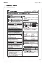
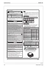
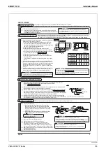
Page 130: ...CAUTION 1 A circuit breaker capable of shutting down power supply to the entire system must be installed 2 A single switch can be used to supply power to units on the same system However branch switches and branch circuit breakers must be selected carefully 3 Fit the power supply wiring of each unit with a switch and fuse as shown in the drawing 4 Be sure to give the electric grounding earth conne...

Page 131: ...5 6 M A V 1 8 3 2 9 1 0 5 1 6 7 4 E V H 0 0 8 M A V 4 0 4 2 9 1 0 5 1 5 0 5 E V H 0 0 0 1 M A V 5 5 7 4 9 1 0 5 1 4 4 9 E V H 0 0 5 1 M A V 7 0 8 4 9 1 0 5 1 9 0 0 1 E V H 0 0 0 2 M A V Power supply wiring Transmission wiring Switch Fuse 1 Outdoor unit 2 Indoor unit 3 Power supply 4 Main switch 5 Remote controller 2 Specifications for field supplied fuses and wire Model g n i r i w n o i s s i m s n...

Page 132: ...ns with the clamp accessory Enlarged view 1 Resinclamp Enlargedview 1 Enlargedview 3 Enlargedview 2 Powersupply wires Earthwire Wiringthrough hole Clamp accessory Clamp accessory forpowersupplywiringandearthwires Clamp accessory forpowersupplywiringandearthwires Cupwasher Clamp accessory Notch Sheetmetal Roundcrimp style terminal Wiring Resinclamp Terminalblock X1M Donotclamplowvoltagewirestogethe...

Page 133: ...y connected to the respective terminal using the specified wires and the sheath section is fixed with a provided clamp ensuring that external forces do not act on the terminal In case of reverse installation Enlarged view 4 Clamp accessory forremotecontrollerwiringandtransmissionwiring Clamp accessory forpowersupplywiringandearthwires Clamp accessory Wiring Push mount y Use the correct screwdriver...

Page 134: ...i W Specifications for external contact Contact that can open and close minimum load DC12V 1mA Model Name VAM150HVE VAM250HVE VAM350HVE VAM500HVE VAM650HVE VAM800HVE VAM1000HVE Power supply Ú1 1 phase 220 240 220V 50 60Hz 1 Fresh up operation Supply air volume can be set at a higher level than the exhaust air Supply Fresh Up or the other way round Exhaust Fresh Up by input from an external contact ...

Page 135: ... 1 5 7 0 e z i s e r i W 2 m 0 5 x a M h t g n e l e r i W Specifications for external contact Contact that can open and close minimum load DC12V 1mA 1 Fresh up operation Supply air volume can be set at a higher level than the exhaust air Supply Fresh Up or the other way round Exhaust Fresh Up by input from an external contact point y Set the fresh up mode to Supply fresh up or Exhaust fresh up on ...

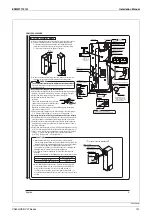
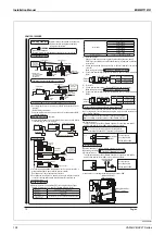
Page 136: ...g position number 4 24 hour ventilation setting NO Ventilation rate1 15 FanOFFfor28 minutes FanONfor2 minutes Ventilation rate1 10 FanOFFfor27 minutes FanONfor3 minutes Ventilation rate1 6 FanOFFfor25 minutes FanONfor5 minutes Ventilation rate1 4 FanOFFfor 22 5minutes FanONfor7 5 minutes Ventilation rate1 3 FanOFFfor20 minutes FanONfor10 minutes Ventilation rate1 2 FanOFFfor 15minute FanONfor15 mi...

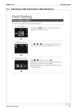
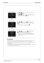
Page 137: ...EDMMT712101 Installation Manual VAM HVE HVLT Series 135 13 2 Field Setting of BRC1H62W White BRC1H62K Black 3P607378 3C ...

Page 138: ...Installation Manual EDMMT712101 136 VAM HVE HVLT Series 3P607378 3C ...

Page 139: ...EDMMT712101 Installation Manual VAM HVE HVLT Series 137 3P607378 3C ...

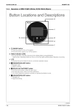
Page 140: ...Installation Manual EDMMT712101 138 VAM HVE HVLT Series 13 3 Operation of BRC1H62W White BRC1H62K Black C EM20A032 ...

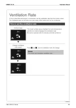
Page 141: ...EDMMT712101 Installation Manual VAM HVE HVLT Series 139 C EM20A032 ...

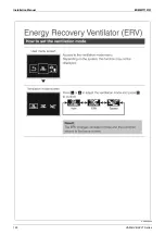
Page 142: ...Installation Manual EDMMT712101 140 VAM HVE HVLT Series C EM20A032 ...

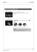
Page 143: ...EDMMT712101 Installation Manual VAM HVE HVLT Series 141 C EM20A032 ...

Page 144: ...duct 2 m K FDS102E K FDS152E K FDS202E CO2 sensor BRYC24A25M BRYC24A35M BRYC24A65M Humidity sensor BRYH241A100 for Return air BRYH242A100 for Outdoor air PM2 5 filtration unit BAF249A150 BAF249A300 BAF249A350 BAF249A500 PM2 5 with activated carbon filtration unit BAF249A150C BAF249A300C BAF249A350C BAF249A500C VAM800HVE VAM800HVLT VAM1000HVE VAM1000HVLT VAM1500HVE VAM1500HVLT VAM2000HVE VAM2000HVL...

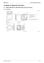
Page 145: ...EDMMT712101 Details of Optional Accessories VAM HVE HVLT Series 143 15 Details of Optional Accessories 15 1 BRC1H62W White BRC1H62K Black Remote Controller 15 1 1 Dimensions 3D132529 Unit mm ...

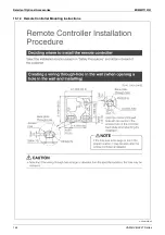
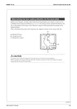
Page 146: ...Details of Optional Accessories EDMMT712101 144 VAM HVE HVLT Series 15 1 2 Remote Controller Mounting Instructions C 3P607378 3C ...

Page 147: ...EDMMT712101 Details of Optional Accessories VAM HVE HVLT Series 145 3P607378 3C ...

Page 148: ...Details of Optional Accessories EDMMT712101 146 VAM HVE HVLT Series 3P607378 3C ...

Page 149: ...EDMMT712101 Details of Optional Accessories VAM HVE HVLT Series 147 3P607378 3C ...

Page 150: ...Details of Optional Accessories EDMMT712101 148 VAM HVE HVLT Series 3P607378 3C ...

Page 151: ...EDMMT712101 Details of Optional Accessories VAM HVE HVLT Series 149 3P607378 3C ...

Page 152: ...Details of Optional Accessories EDMMT712101 150 VAM HVE HVLT Series 3P607378 3C ...

Page 153: ...EDMMT712101 Details of Optional Accessories VAM HVE HVLT Series 151 15 2 BRC1E63 Remote Controller 15 2 1 Dimensions 3D106191 Unit mm ...

Page 154: ...Details of Optional Accessories EDMMT712101 152 VAM HVE HVLT Series 15 2 2 Remote Controller Mounting Instructions C 4P457318 1D ...

Page 155: ...EDMMT712101 Details of Optional Accessories VAM HVE HVLT Series 153 4P457318 1D ...

Page 156: ...Details of Optional Accessories EDMMT712101 154 VAM HVE HVLT Series 4P457318 1D ...

Page 157: ...EDMMT712101 Details of Optional Accessories VAM HVE HVLT Series 155 4P457318 1D ...

Page 158: ...Details of Optional Accessories EDMMT712101 156 VAM HVE HVLT Series 4P457318 1D ...

Page 159: ...EDMMT712101 Details of Optional Accessories VAM HVE HVLT Series 157 4P457318 1D ...

Page 160: ...WDJH QRUPDOO RSHQ FRQWDFW 9 RU OHVV 2XWSXW WKH DEQRUPDOLW GLVSOD VLJQDO WR DQ H WHUQDO GHYLFH 3LORW ODPS 㹙 53 㹛 㼄㻝㻭 㼃㼕㼞㼑㻌㼏㼘㼍㼙㼜 㼃㼕㼞㼕㼚㼓㻌㼠㼔㼞㼛㼡㼓㼔㻙㼔㼛㼘㼑㻌㻔㼘㼛㼣㼑㼞㻕 33 02 KHFN WKH DSSOLFDEOH PRGHO RI WKLV NLW 9 0 2 9 9 0 2 9 7 9 0 2 9 9 0 2 9 7 9 0 2 9 9 0 2 9 7 9 0 9 9 0 9 7 9 0 9 9 0 9 7 9 0 9 9 0 9 7 9 0 9 9 0 9 7 9 0 9 9 0 9 7 9 0 9 9 0 9 7 33 02 ە 3DVV WKH VLJQDO ZLUH RI WKH GDSWRU IRU ZLULQJ WKURXJK W...

Page 161: ...5 4 KRP1C18A90 Installation Box for Adaptor Printed Circuit Board 15 4 1 Dimensions JC 3D120782 Unit mm Specifications Accessories Mounting plate Mounting plate Hot dip galvanized steel sheet Lid Hot dip galvanized steel sheet Mounting screw 4 pcs Installation manual Lid ...

Page 162: ...㻌㻼㼞㼛㼢㼕㼐㼑㼐㻌㼣㼕㼠㼔㻌㼠㼔㼑㻌㼣㼕㼞㼕㼚㼓㻌㼍㼐㼍㼜㼠㼛㼞 㻌㼒㼛㼞㻌㼑㼘㼑㼏㼠㼞㼕㼏㼍㼘㻌㼍㼜㼜㼑㼚㼐㼕㼏㼑㼟 1 7 5 6 㻼㼍㼟㼟㻌㼠㼔㼑㻌㼣㼕㼞㼑 㼠㼔㼞㼛㼡㼓㼔 㻭㼐㼍㼜㼠㼛㼞㻌㼒㼛㼞㻌㼣㼕㼞㼕㼚㼓 㼃㼕㼞㼕㼚㼓㻌㼍㼐㼍㼜㼠㼛㼞㻌㼒㼛㼞㻌㼑㼘㼑㼏㼠㼞㼕㼏㼍㼘㻌㼍㼜㼜㼑㼚㼐㼕㼏㼑㼟 㻼㼍㼟㼟㻌㼠㼔㼑㻌㼣㼕㼞㼑㻌㼠㼔㼞㼛㼡㼓㼔 㸰 㻯㼘㼍㼙㼜㻌㼙㼍㼠㼑㼞㼕㼍㼘 02817 1 3725 35 17 5 8 7 2 5 51 1 KHQ FRQQHFWLQJ WKH ILHOG ZLUHV WR HDFK DGDSWRU XVH WKH ZLUHV DQG WHUPLQDOV WKDW VDWLVI WKH IROORZLQJ FRQGLWLRQV 3725 1 0 211 7 7 50 1 2 5 7 1 66 7 50 1 7 3 GDSWRU IRU ZLULQJ LU...

Page 163: ...O DQG FRQQHFW WKH WUDQVPLVVLRQ ZLUHV WR DQG RI WKH WHUPLQDO EORFN RQQHFW WKH VLJQDO ZLUH RI WKH DGDSWRU IRU ZLULQJ WR WKH FRQQHFWRU RQ WKH XQLW V SULQWHG FLUFXLW ERDUG LQG XS WKH H FHVV ZLUHV DQG IL WKHP ZLWK WKH ZLUH FODPS LQVLGH WKH VZLWFK ER OWKRXJK WKH VKDSH RI WKH VZLWFK ER ZLOO EH GLIIHUHQW IRU 9 0 9 DQG 9 0 9 WKH PHWKRG RI SDVVLQJ WKURXJK WKH ZLUHV IRU HDFK DGDSWRU SULQWHG FLUFXLW ERDUG DQG...

Page 164: ...0 m3 h Caution The silencer cannot be used on different model Confirm the model before installation 15 5 1 Dimensions KDDM24B100 Part No KDDM24B100 Applicable model VAM500HVE VAM650HVE VAM500HVLT VAM650HVLT VAM800HVE VAM1000HVE VAM1500HVE VAM2000HVE VAM800HVLT VAM1000HVLT VAM1500HVLT VAM2000HVLT Nominal pipe diameter 200 mm 250 mm Noise suppression effect Approx 6 dB hole hole J D3K03771B Characte...

Page 165: ...M series 3 Use the provided screws and install the flange on the Heat Reclaim Ventilator VAM series 4 Install the body of silencer on the flange Then install the duct coupling Installation procedure of duct 1 Insert the duct into the duct coupling and wind round the commercially available aluminum tape etc to prevent the air leakage Body of silencer Flange Duct coupling Air supply side of indoor u...

Page 166: ...E VAM250HVLT KAF241J50M VAM350HVE VAM350HVLT 2 1 KAF241J65M VAM500HVE VAM500HVLT 2 1 VAM650HVE VAM650HVLT KAF241K100M VAM800HVE VAM800HVLT 2 1 VAM1000HVE VAM1000HVLT VAM1500HVE VAM1500HVLT 2 VAM2000HVE VAM2000HVLT Working ambient temperature 15 to 50 C Working ambient humidity 85 RH Pressure loss Initial loss Less than 15 Pa Final loss Less than 78 Pa Life Over 2500 hours Dust density 0 10 mg m3 A...

Page 167: ...ls of Optional Accessories VAM HVE HVLT Series 165 KAF241J50M KAF241J65M Unit mm JC 3D115515 KAF241K100M Part No AA AB KAF241J50M 724 172 KAF241J65M 756 203 Bendable part center JC 3D120784 Unit mm Bendable part center ...

Page 168: ...e conditions Ambient temperature 0 50 C Relative humidity 40 95 Initial pressure loss 24 5 Pa 2 5 mmH2O or less Final pressure loss 78 4 Pa 8 mmH2O or less Average dust collecting efficiency 65 Colorimetric method Life time Over 2500 hours Outdoor dust density 0 15 mg m3 VAM1500 2000 need 2 sets per one unit Part No AA AB Airflow rate KAF242J25M 469 167 225 KAF242J50M 366 177 225 KAF242J65M 382 20...

Page 169: ...0HVLT VAM1500HVLT VAM2000HVLT Nominal diameter 100 150 200 250 Duct length 1 m 101E 151E 201E 251E 2 m 102E 152E 202E 252E Connection diameter Filament Steel plate zinc treated t0 5 Terminal treatment material fabric tape Details of Z Non woven fabric Heat insulating material glass wool 24kg m3 thickness 25mm Outer face covering material polypropylene resin film Recommended use range Maximum airfl...

Page 170: ...cing be sure that the power supply to the unit is disconnected and keep sufficient distance from existing wires Otherwise it may result in electric shocks This product is not a measurement instrument based on the Measurement Act Do not use this product as a safety device in purpose to detect toxic gas or flammable gas that causes oxygen deficiency or carbon monoxide intoxication Follow the install...

Page 171: ...ation Details 1 Remove the 2 fixing screws of the electrical box then open the electrical box 2 Bring out the wire from the inside of the unit through the lower bush weak elec wire side then firmly insert it to the X14A connector white on the print circuit board A1P See Arrow View A 3 Bundle the CO2 sensor wire and damper wire red together with the indoor thermistor wire by the 2 clamps so that th...

Page 172: ...al box and check the connection are connected properly b Wire disconnection o Contact your dealer c Failure in the CO2 sensor o Contact your dealer CAUTION After completion of the test run check that the heat exchanger elements and air filters are installed in the correct position and the service cover and the electrical box are installed properly OPERATION PROCEDURE Set the Fresh Up mode by the v...

Page 173: ...EDMMT712101 Psychrometric Chart VAM HVE HVLT Series 171 16 Psychrometric Chart 16 1 Psychrometric Chart ...

Page 174: ...d to natural ventilation Maintaining negative pressure is necessary for ventilation of a room with highly polluted air in order to avoid the outflow of polluted air to adjacent rooms or hallways Class 1 Ventilation or Class 3 Ventilation Likewise positive pressure is necessary to prevent the inflow of polluted air to rooms requiring cleanliness Class 2 Ventilation Exhaust air o Mechanical ventilat...

Page 175: ...Generally the installation area for the ventilator is made larger The installation area is made large enough for the incoming air velocity to be small and prevent any discomfort to the people near the air opening 2 Position of Exhaust Ventilator and Air Supply Opening For general ventilation the supply air openings are installed in locations that are as far as possible from the ventilators In case...

Page 176: ... force to send air out that overcomes resistance of the duct Dynamic pressure Pv is the direction of pressure for the flow of wind and is used at the time of measuring wind speed Total pressure Pt expresses static pressure added to dynamic pressure 17 2 4 P Q Curve Static Pressure Airflow Rate Special Feature Curve The relationship between ventilator airflow rate and static pressure can be seen in...

Page 177: ... don t face exterior walls or places in which the outside wind is strong Air Velocity and Wind Pressure Reference Values Propeller Fan The axial blower is extremely small and simple Although airflow rate is large because static pressure is relatively low at 0 30 Pa airflow rate substantially decreases when airflow encounters resistance such as from a duct Sirocco Fan Sirocco fans have multiple blo...

Page 178: ...ng the following three items when employing these values 1 Sound Changing Environments The measurement values were measured in an anechoic chamber There are reverberations from walls floors ceilings etc in an actual building so please consider the reverberation coefficient of the room since values increase according to the material quality of surroundings and size 2 Vibration Propagation Products ...

Page 179: ...bends Select the model that satisfies the characteristics according to Static Pressure and Airflow Rate Characteristics Allow leeway of 10 20 for gained pressure loss and make necessary static pressure Find intersection by entering Bend Pressure Resistance to Bend Static Pressure and Airflow Rate Characteristics Find pressure loss for duct system overall Find Local Pressure Loss by the Local Loss ...

Page 180: ...w rate m3 h Here when we substitute λ 0 01 in the case that the pipe is extremely smooth γ 1 2 P 0 01 γ 2 L d Q d2 4 3 600 π Q d2 2 1 2 2 L d 4 3 600π Duct material Aluminum flexible duct Vinyl chloride pipe Galvanized steel pipe λ 0 03 to 0 04 0 01 to 0 02 0 016 to 0 025 1000000 800000 600000 400000 200000 100000 80000 60000 40000 20000 10000 8000 6000 4000 2000 1000 800 600 400 200 100 80 60 40 ...

Page 181: ...nd multiply it by duct length to get 11 Pa Calculation to Circular Duct from Rectangular Duct 2 2 0 300 Airflow rate Q m 3 h A i r v e l o c i t y v m s d 15 cm Friction loss coefficient Pa m B A Long side Short side Equivalent diam eter 200 D e 9 0 Long side Short side Example For a rectangular duct of 40 200 the corresponding diameter of a circular duct is 90 I Find the intersection A for the sh...

Page 182: ...sure loss is converted to duct diameter However because the value expressed here belongs to friction resistance coefficient γ 0 018 of time please use the following formula for other cases re Partial resistance for equivalent length of straight pipe m re d d Straight pipe diameter m ζ Local pressure loss v2 2 No 1 2 3 4 5 6 Name Shape diagram Condition H W 0 25 0 5 1 0 4 0 0 5 0 75 1 0 1 5 θ θ 0 5...

Page 183: ...ht pipe 9 m A rough estimate when using λ 0 02 galvanized steel pipe Ventilator for duct Parts I II III IV V VI Total 0 5 m 2 m 0 5 m 2 m 5 m 9 m 19 m 3 When finding from the equivalent length of straight pipe re and airflow rate Q Example When selecting a model that satisfies performance Equivalent length of straight pipe 19 m Airflow rate 120 m3 h Drop a vertical line from intersection A of the ...

Page 184: ......

Page 185: ......

Page 186: ......

Page 187: ......

Page 188: ...tractor to install this product Do not try to install the product yourself Improper installation can result in water or refrigerant leakage electrical shock fire or explosion Use only those parts and accessories supplied or specified by Daikin Ask a qualified installer or contractor to install those parts and accessories Use of unauthorised parts and accessories or improper installation of parts a...

Reviews: