EDMMT712101
Details of Optional Accessories
VAM-HVE/HVLT Series
169
JC: 2P550746-1D
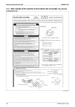
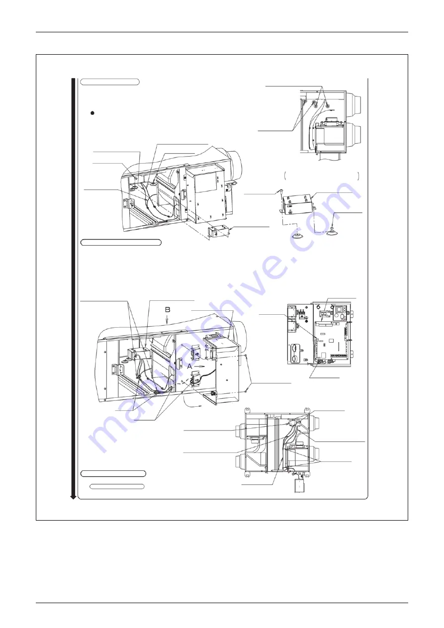
2. CO
2
sensor installation
3. Wiring connection of CO
2
sensor
CO
2
Sensor Fixing Screw
Humidity Sensor
(indoor side)
Fixing Screw
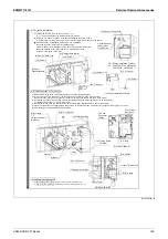
(1) Loosen the screw 2, then remove the screw 1 (
※
1).
(
※
1): The screw positions may differ depending on models.
(2) Install the CO
2
sensor as shown in the figure and tighten the screw 1 and 2.
(
※
2): Be careful not to get the damper wire or indoor thermistor wire caught in the sensor.
For VAM150H(S), VAM250H(S), VAM150HS, and VAM250HS,
the humidity sensor (indoor side) is installed nearby.
If the CO
2
sensor is not installed properly, the humidity sensor (indoor side)
cannot be installed in the correct position so install the CO
2
sensor
as shown in the figure on the right.
(2) Damper Wire (red)
(1)(2) Screw 2
(2) Indoor
Thermistor wire
(2) Damper Wire (white)
(1)(2) Screw 1
(2) CO
2
Sensor
(1)(2) Screw 2
CO
2
Sensor Installation Position
For VAM150H(S)
・
VAM250H(S)
VAH150HS
・
VAH250HS
(2) CO
2
Sensor
(1)(2) Screw 1
CO
2
Sensor Installation Details
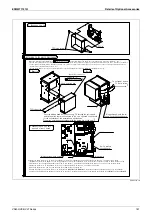
(1) Remove the 2 fixing screws of the electrical box, then open the electrical box.
(2) Bring out the wire from the inside of the unit through the lower bush (weak elec. wire side),
then firmly insert it to the X14A connector (white) on the print circuit board A1P. (See Arrow View A)
(3) Bundle the CO
2
sensor wire and damper wire (red) together with the indoor thermistor wire by the 2 clamps
so that there is no stack (
※
1, See Arrow View B).
(4) Bundle the excess wires and secure them with the clamp inside the electrical box. (See Arrow View A)
(5) Close the electrical box and tighten the 2 fixing screws on the electrical box, be careful not to get any wire caught by the screws.
(6) After binding, cut off the excess edge of the clamp.
(3)(6) Clamp
※
1
Fix near the clamp
(2 places)
(2)(3) CO
2
Sensor
(1)(5) Electrical Box
Clamp
(2) Bush
Open
(1)(5) Fixing Screw
(2 places)
(2) X14A
Connector
(white)
Print Citcuit
Board A1P
(4) Clamp
Arrow View A
Arrow View B
(2)(3) CO
2
Sensor
(3) Damper Wire (red)
(3) No Slack
(3) Indoor Thermistor Wire
(3)(6) Clamp
(3) No Slack
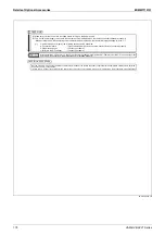
4. Installing the components
Close the electrical box, then install the components with the procedure of
1. Removing the components , install the parts in the following order (2)
o
(1).
Summary of Contents for VAM Series
Page 2: ......
Page 4: ...EDMMT712101 2 Table of Contents 17 6 Precautions for Design and Installation 181 ...
Page 56: ...Control System EDMMT712101 54 VAM HVE HVLT Series C 3P343420 1E ...
Page 138: ...Installation Manual EDMMT712101 136 VAM HVE HVLT Series 3P607378 3C ...
Page 139: ...EDMMT712101 Installation Manual VAM HVE HVLT Series 137 3P607378 3C ...
Page 141: ...EDMMT712101 Installation Manual VAM HVE HVLT Series 139 C EM20A032 ...
Page 142: ...Installation Manual EDMMT712101 140 VAM HVE HVLT Series C EM20A032 ...
Page 143: ...EDMMT712101 Installation Manual VAM HVE HVLT Series 141 C EM20A032 ...
Page 147: ...EDMMT712101 Details of Optional Accessories VAM HVE HVLT Series 145 3P607378 3C ...
Page 148: ...Details of Optional Accessories EDMMT712101 146 VAM HVE HVLT Series 3P607378 3C ...
Page 149: ...EDMMT712101 Details of Optional Accessories VAM HVE HVLT Series 147 3P607378 3C ...
Page 150: ...Details of Optional Accessories EDMMT712101 148 VAM HVE HVLT Series 3P607378 3C ...
Page 151: ...EDMMT712101 Details of Optional Accessories VAM HVE HVLT Series 149 3P607378 3C ...
Page 152: ...Details of Optional Accessories EDMMT712101 150 VAM HVE HVLT Series 3P607378 3C ...
Page 155: ...EDMMT712101 Details of Optional Accessories VAM HVE HVLT Series 153 4P457318 1D ...
Page 156: ...Details of Optional Accessories EDMMT712101 154 VAM HVE HVLT Series 4P457318 1D ...
Page 157: ...EDMMT712101 Details of Optional Accessories VAM HVE HVLT Series 155 4P457318 1D ...
Page 158: ...Details of Optional Accessories EDMMT712101 156 VAM HVE HVLT Series 4P457318 1D ...
Page 159: ...EDMMT712101 Details of Optional Accessories VAM HVE HVLT Series 157 4P457318 1D ...
Page 184: ......
Page 185: ......
Page 186: ......
Page 187: ......

