Product Introduction
EDMMT712101
16
VAM-HVE/HVLT Series
1.4
Selection Procedures
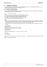
Various methods are used to calculate the required ventilating airflow rate according to CO
2
generated by inhabitants in a room,
waste gas generated by use of fire, and other conditions of a room.
Here are 2 patterns of calculating methods.
1.4.1
Based on Breathing Zones
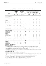
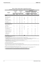
The outdoor airflow required in the breathing zone (
Vbz
) of the occupiable space or spaces in a ventilation zone shall be not less
than the value determined in accordance with Equation 1.
Vbz
=
Rp
×
Pz
+
Ra
×
Az
(1)
where
Az
= zone floor area, the net occupiable floor area of the ventilation zone, ft² (m²)
Pz
= zone population, the number of people in the ventilation zone during use
Rp
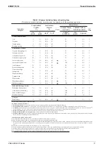
= outdoor airflow rate required per person as determined from Table 1
Ra
= outdoor airflow rate required per unit area as determined from Table 1
The above equation conforms to ASHRAE Standard 62.1-2019
Notes:
1. Equation 1 accounts for people-related sources and area-related sources independently in the determination of the outdoor air
rate required at the breathing zone. The use of Equation 1 in the context of this standard does not necessarily imply that simple
addition of outdoor airflow rates for different sources can be applied to any other aspect of IAQ.
2. Design zone population (
Pz
) shall equal the largest (peak) number of people expected to occupy the ventilation zone during
typical use.
(Selection example)
Place: Break rooms
Outdoor air flow rate required per person: 5 cfm/person
Outdoor air flow rate required per unit area: 0.06 cfm/ft²
Zone population: 17
Zone floor area: 20 ft²
Required ventilating airflow rate = 5 × 17 + 0.06 × 20 = 86.2 cfm = 146 m³/h
Conversion:
1 L/s = 3.6 m³/h
1 cfm = 1.699 m³/h
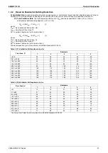
Required ventilating airflow rate and the unit size such as 150, 250, 350 .......2000 are almost equal. So select the close size of the
unit.
In this case, select VAM150HVE/HVLT
Summary of Contents for VAM Series
Page 2: ......
Page 4: ...EDMMT712101 2 Table of Contents 17 6 Precautions for Design and Installation 181 ...
Page 56: ...Control System EDMMT712101 54 VAM HVE HVLT Series C 3P343420 1E ...
Page 138: ...Installation Manual EDMMT712101 136 VAM HVE HVLT Series 3P607378 3C ...
Page 139: ...EDMMT712101 Installation Manual VAM HVE HVLT Series 137 3P607378 3C ...
Page 141: ...EDMMT712101 Installation Manual VAM HVE HVLT Series 139 C EM20A032 ...
Page 142: ...Installation Manual EDMMT712101 140 VAM HVE HVLT Series C EM20A032 ...
Page 143: ...EDMMT712101 Installation Manual VAM HVE HVLT Series 141 C EM20A032 ...
Page 147: ...EDMMT712101 Details of Optional Accessories VAM HVE HVLT Series 145 3P607378 3C ...
Page 148: ...Details of Optional Accessories EDMMT712101 146 VAM HVE HVLT Series 3P607378 3C ...
Page 149: ...EDMMT712101 Details of Optional Accessories VAM HVE HVLT Series 147 3P607378 3C ...
Page 150: ...Details of Optional Accessories EDMMT712101 148 VAM HVE HVLT Series 3P607378 3C ...
Page 151: ...EDMMT712101 Details of Optional Accessories VAM HVE HVLT Series 149 3P607378 3C ...
Page 152: ...Details of Optional Accessories EDMMT712101 150 VAM HVE HVLT Series 3P607378 3C ...
Page 155: ...EDMMT712101 Details of Optional Accessories VAM HVE HVLT Series 153 4P457318 1D ...
Page 156: ...Details of Optional Accessories EDMMT712101 154 VAM HVE HVLT Series 4P457318 1D ...
Page 157: ...EDMMT712101 Details of Optional Accessories VAM HVE HVLT Series 155 4P457318 1D ...
Page 158: ...Details of Optional Accessories EDMMT712101 156 VAM HVE HVLT Series 4P457318 1D ...
Page 159: ...EDMMT712101 Details of Optional Accessories VAM HVE HVLT Series 157 4P457318 1D ...
Page 184: ......
Page 185: ......
Page 186: ......
Page 187: ......


