Control System
EDMMT712101
24
VAM-HVE/HVLT Series
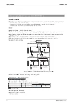
POINT
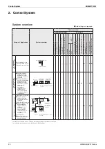
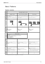
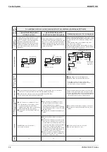
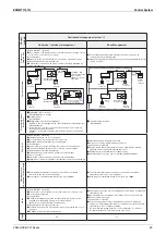
Sample system
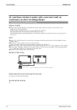
1. When zone interlock is set to “Yes”, priority
is given to energy-saving interlocked control
with commercial multi air conditioners (building
multi). Therefore, individual start/stop of Heat
Reclaim Ventilator Unit cannot be performed
with the central remote controller or Unified ON/
OFF controller.
If there are no commercial multi air conditioners
(building multi) to be interlocked within the
zone, set the zone interlock to “No”. (
③
and
④
on the right)
2. When zone interlock is set to “No”, priority is
given to independent start/stop of Heat Reclaim
Ventilator Unit. Accordingly, energy-saving
interlocked control is not performed.
3. Generally, do not set the precooling/preheating
operation when independent ventilation
operation is started/stopped with a centralized
control equipment. If the precooling/preheating
operation is set, the unit will start operating
after the set time has elapsed.
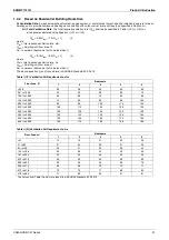
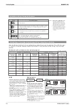
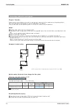
Introduction to Major Connection Terminals
Terminal
Function Descriptions
Notes) 1. All the system configurations in this
section use commercial multi air
conditioners (building multi) as an
example. The same controls can be
performed when the air conditioners
are replaced with the SkyAir series.
2.
The system configurations in this
section use wired remote controllers
as an example. The same applies
to the cases using wireless remote
controllers.
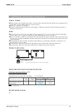
Power supply
L N
Power terminal
Remote controller
P1 P2
A remote controller connection terminal and connection terminal for energy-
saving interlocking with indoor unit of commercial multi air conditioners
(building multi)/SkyAir.
Central
F1 F2
This terminal receives information when centralized control equipment is
connected.
External
input
J
1
J
2
J
3
JC
(J1), (JC) terminal Fresh-up operation by external input
(J2), (JC) terminal Distant control by external input
Please refer to pages 42-44 for switching to other functions.
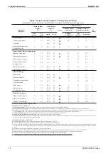
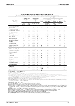
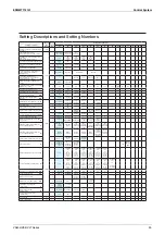
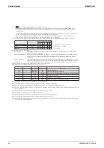
Field Settings of “Centralized Zone Interlock Setting” Using Remote Controller
When Heat Reclaim Ventilator Unit is connected to the centralized transmission line (between (F1) and (F2) terminals),
it is necessary to consider changing the default field setting of “centralized zone interlock setting” using the remote
controller.
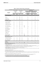
Combination with centralized control-related equipment
○
: Possible ×: Impossible
Centralized control-related equipment
Operations / Functions
Field setting
(Centralized zone
interlock setting)
Central remote
controller
Unified
ON/OFF
controller
schedule
timer
Wiring adapter
for electrical
appendices
Energy saving
interlocking
(Automatic judgement)
Start/Stop
(from centralized
control)
1~4 units
−
−
−
〇
×
Yes
×
×
No
1~4 units
1~16 units
−
−
〇
×
Yes
×
〇
No
1~4 units
−
1 unit
−
〇
×
Yes
×
×
No
1~4 units
1~16 units
1 unit
−
〇
×
Yes
×
〇
No
−
1~16 units
−
−
Simultaneous operation is not available.
−
×
〇
No
−
1~16 units
1 unit
−
Simultaneous operation is not available.
−
×
〇
No
−
−
1 unit
−
〇
×
Yes
×
×
(
Batch ON/OFF only)
No
−
−
−
1 unit
〇
×
Yes
×
×
(
Batch ON/OFF only)
No
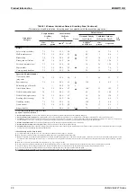
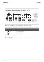
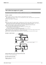
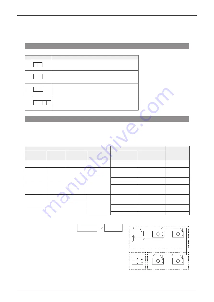
③
④
⑤
②
①
Central remote
controller
Unified ON/OFF
controller
Zone1
Remote controller
Zone 3
Zone interlock
“Yes”
Zone interlock
“Yes”
Zone 2
Zone interlock
“No”
Zone interlock
“No”
Zone interlock
“No”
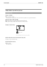
About
①
Basically, the operations and displays that
are performed using remote controller for air
conditioner can be carried out with the central
remote controller. However, it is not possible
to carry out independent ventilation operation,
ventilation mode switching and air volume
switching using the central remote controller.
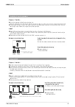
About
②
It interlocks with indoor units within the same
zone. Independent ventilation operation mode can
be set on the central remote controller.
Independent operation cannot be performed using
the Unified ON/OFF controller.
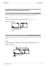
About
⑤
When a central remote controller is used and zone
control of multiple units is not performed, one unit
becomes one zone.
To change ventilation rate, etc. other than the field
settings, connect the remote controller to Heat
Reclaim Ventilator Unit.
For other details, please see page 59.
Summary of Contents for VAM Series
Page 2: ......
Page 4: ...EDMMT712101 2 Table of Contents 17 6 Precautions for Design and Installation 181 ...
Page 56: ...Control System EDMMT712101 54 VAM HVE HVLT Series C 3P343420 1E ...
Page 138: ...Installation Manual EDMMT712101 136 VAM HVE HVLT Series 3P607378 3C ...
Page 139: ...EDMMT712101 Installation Manual VAM HVE HVLT Series 137 3P607378 3C ...
Page 141: ...EDMMT712101 Installation Manual VAM HVE HVLT Series 139 C EM20A032 ...
Page 142: ...Installation Manual EDMMT712101 140 VAM HVE HVLT Series C EM20A032 ...
Page 143: ...EDMMT712101 Installation Manual VAM HVE HVLT Series 141 C EM20A032 ...
Page 147: ...EDMMT712101 Details of Optional Accessories VAM HVE HVLT Series 145 3P607378 3C ...
Page 148: ...Details of Optional Accessories EDMMT712101 146 VAM HVE HVLT Series 3P607378 3C ...
Page 149: ...EDMMT712101 Details of Optional Accessories VAM HVE HVLT Series 147 3P607378 3C ...
Page 150: ...Details of Optional Accessories EDMMT712101 148 VAM HVE HVLT Series 3P607378 3C ...
Page 151: ...EDMMT712101 Details of Optional Accessories VAM HVE HVLT Series 149 3P607378 3C ...
Page 152: ...Details of Optional Accessories EDMMT712101 150 VAM HVE HVLT Series 3P607378 3C ...
Page 155: ...EDMMT712101 Details of Optional Accessories VAM HVE HVLT Series 153 4P457318 1D ...
Page 156: ...Details of Optional Accessories EDMMT712101 154 VAM HVE HVLT Series 4P457318 1D ...
Page 157: ...EDMMT712101 Details of Optional Accessories VAM HVE HVLT Series 155 4P457318 1D ...
Page 158: ...Details of Optional Accessories EDMMT712101 156 VAM HVE HVLT Series 4P457318 1D ...
Page 159: ...EDMMT712101 Details of Optional Accessories VAM HVE HVLT Series 157 4P457318 1D ...
Page 184: ......
Page 185: ......
Page 186: ......
Page 187: ......


