Control System
EDMMT712101
26
VAM-HVE/HVLT Series
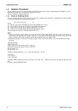
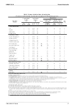
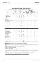
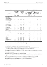
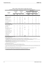
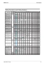
Note) 1.
The factory default setting position is displayed in the frame.
2.
Setting items with two-digit setting switch numbers (10 or more) can be set only from remote controller BRC1E63 or later.
3.
The settings are applied to the entire group, but if the mode number inside the ( ) is selected, the setting can be applied to
individual units.
However, the confirmation of setting change can only be made for the individual modes inside the ( ). (In case of entire group
setting, the display shows the factory default setting even after the setting is changed.)
4.
Do not make settings that are not listed above. Also, the setting will not be displayed if there is no corresponding function.
5.
When returning to the normal mode, the remote controller may display “88” for initialization.
★
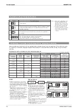
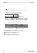
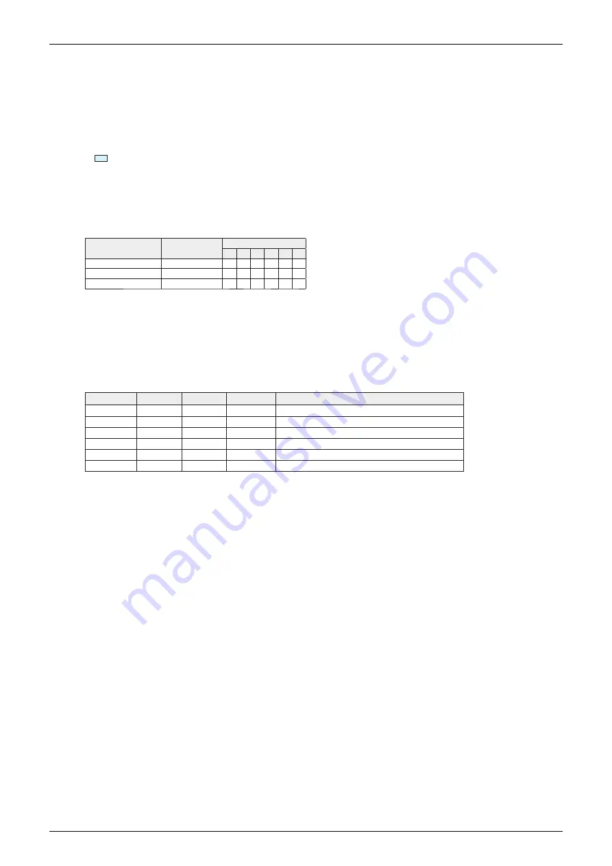
1. The details of cold region operation setting are as follows. (This setting is enabled only when interlocked with air conditioner)
Air conditioner fan
Heat Reclaim Ventilator Unit fan
01
02
03
04
05
06
Heating thermostat OFF
Operation
—
—
S
L
S
L
—: Operates at the set airflow rate
Defrost
Stop
—
S
S
S
S
S
L : Operates at low airflow
Oil return
Stop
—
S
S
S
S
S
S : Stopped
★
2. Details of external input setting
“Last command”
.......................
Only during independent operation of Heat Reclaim Ventilator Unit. External input is not allowed when
interlocked with air conditioner.
“Priority on external input”
...
Remote controller is prohibited when the unit is “started” by external input. Remote controller is allowed
when the unit is “stopped” by external input. External input is not allowed when interlocked with air
conditioner.
“Priority on operation”
............
The unit operates when either the remote controller for the air conditioner or external input is set to “start”
when interlocked with air conditioner. This setting can be made only during interlock with air conditioner.
“Forced OFF”
.............................
The unit stops operation at the occurrence of a contact input by external input. (No automatic recovery)
★
3. This setting can be made when a CO
2
sensor (optional accessory) is used.
★
4. The details of external input terminal functions are as follows.
Setting position
Input contact
Fan operation Operation lamp
Behaviors
01
a
Operation
ON
Fresh-up operation
02
a
Operation
ON
Error code “60” displayed, fan ON
03
a
Stop
Blinking
Error code “60” displayed, fan OFF, automatic recovery available
04
b
Stop
OFF
No automatic recovery
05
b
Stop
ON
Automatic recovery available
06
a
Operation
ON
Airflow rate increase (Low
→
High/Ultra high)
★
5. This setting can be made only from the remote controller BRC1H62.
★
6. This setting is made to shift the base CO
2
concentration used as a reference (unit: ppm).
★
7. This is the setting to permit Step 0 (OFF for 10 minutes) when “Linear” is selected on the table setting.
★
8. This is the setting to enhance outside air cooling effect by increasing the airflow rate of Bypass mode when the ventilation air volume
“Auto” is selected.
★
9. This setting can be made when a humidity sensor (optional accessory) is used.
★
10. The figure in ( ) shows the estimated daily operating hours.
★
11. This setting can be made when an indoor humidity sensor (optional accessory) is used.
★
12. This setting can be made when adapter for wiring (optional accessory) is used.
★
13. As with normal operating run by on signal from remote controller, do not use the unit beyond the operating temperature range even
during 24-hour ventilation operation.
Summary of Contents for VAM Series
Page 2: ......
Page 4: ...EDMMT712101 2 Table of Contents 17 6 Precautions for Design and Installation 181 ...
Page 56: ...Control System EDMMT712101 54 VAM HVE HVLT Series C 3P343420 1E ...
Page 138: ...Installation Manual EDMMT712101 136 VAM HVE HVLT Series 3P607378 3C ...
Page 139: ...EDMMT712101 Installation Manual VAM HVE HVLT Series 137 3P607378 3C ...
Page 141: ...EDMMT712101 Installation Manual VAM HVE HVLT Series 139 C EM20A032 ...
Page 142: ...Installation Manual EDMMT712101 140 VAM HVE HVLT Series C EM20A032 ...
Page 143: ...EDMMT712101 Installation Manual VAM HVE HVLT Series 141 C EM20A032 ...
Page 147: ...EDMMT712101 Details of Optional Accessories VAM HVE HVLT Series 145 3P607378 3C ...
Page 148: ...Details of Optional Accessories EDMMT712101 146 VAM HVE HVLT Series 3P607378 3C ...
Page 149: ...EDMMT712101 Details of Optional Accessories VAM HVE HVLT Series 147 3P607378 3C ...
Page 150: ...Details of Optional Accessories EDMMT712101 148 VAM HVE HVLT Series 3P607378 3C ...
Page 151: ...EDMMT712101 Details of Optional Accessories VAM HVE HVLT Series 149 3P607378 3C ...
Page 152: ...Details of Optional Accessories EDMMT712101 150 VAM HVE HVLT Series 3P607378 3C ...
Page 155: ...EDMMT712101 Details of Optional Accessories VAM HVE HVLT Series 153 4P457318 1D ...
Page 156: ...Details of Optional Accessories EDMMT712101 154 VAM HVE HVLT Series 4P457318 1D ...
Page 157: ...EDMMT712101 Details of Optional Accessories VAM HVE HVLT Series 155 4P457318 1D ...
Page 158: ...Details of Optional Accessories EDMMT712101 156 VAM HVE HVLT Series 4P457318 1D ...
Page 159: ...EDMMT712101 Details of Optional Accessories VAM HVE HVLT Series 157 4P457318 1D ...
Page 184: ......
Page 185: ......
Page 186: ......
Page 187: ......

