EDMMT712101
Control System
VAM-HVE/HVLT Series
29
Contr
ol
method
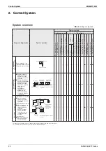
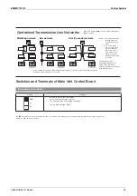
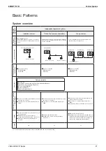
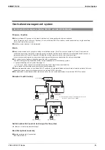
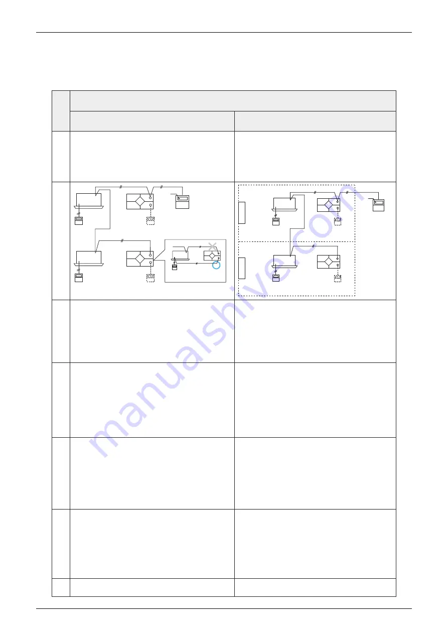
Centralized management system
※
1
Collective / individual management
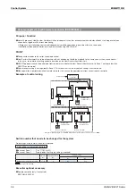
Zone Management
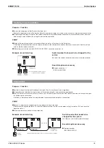
Purpose • Application
[Unified ON / OFF controller]
The start/stop of 16 groups can be controlled with one controller. Up to 8
units can be connected in one system.
[Schedule timer]
128 units can be controlled with one controller on a weekly schedule.
[Wiring adapter for electrical appendices]
A maximum of 128 units in 64 groups can be collectively managed by
using one adapter.
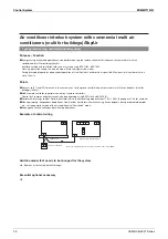
Zone management is possible whereby the same control can be
collectively set for multiple groups.
Independent ventilation operation by zone can be performed with central
remote controller.
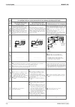
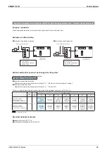
System overview
Heat Reclaim
Ventilator Unit
Power
supply
Heat Reclaim
Ventilator Unit
Indoor
unit
Unified ON / OFF
controller or Schedule
timer or Wiring
adapter for electrical
appendices
●
To perform interlocking operation,
connect to the centralized
terminal of the air conditioner.
Remote
controller
Remote
controller
Remote
controller
Remote
controller
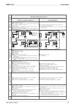
Indoor
unit
Heat Reclaim
Ventilator Unit
Remote
controller
Remote
controller
Indoor
unit
Heat Reclaim
Ventilator Unit
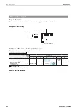
Zone 1
Zone 2
Central
remote
controller
Power
supply
Remote
controller
Indoor
unit
Essential optional
accessory
█
Unified ON / OFF controller
DCS301BA61 (up to 8 units)
█
Schedule timer
DST301BA61
█
Wiring adapter for electrical appendices
(Unable to use in combination with other centralized control equipment)
KRP2A61•62•63
※
Incorporate one of the above models into the applicable commercial multi
air conditioner (multi for buildings).
KRP2A62 if incorporated in Heat Reclaim Ventilator Unit. (Use an applicable
model)
█
Central remote controller
DCS302CA61
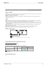
Functions
[Unified ON / OFF controller]
Individual start/stop can be set by group
Batch start/stop is possible for each of 16 groups.
Equipped with power terminal for schedule timer.
[Schedule timer]
It is possible to set batch start/stop twice a day on a weekly basis.
With 48 hour backup time for each occurrence of power failure.
[Wiring adapter for electrical appendices]
Simultaneous batch start/stop is possible by external input.
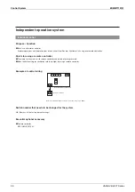
[Remote controller]
Interlocked operation with air conditioner can be performed.
Independent operation of Heat Reclaim Ventilator Unit can be performed.
Individual or batch start/stop is possible.
A zone consisting of multiple groups can be set.
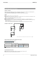
[Central remote controller]
Energy-saving interlocking operation can be performed by starting/
stopping an air conditioner within the same zone.
Equipped with power terminal for schedule timer.
Ventilation rate and mode can be switched with DCS302CA61.
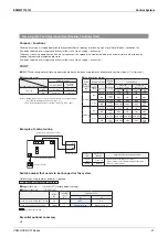
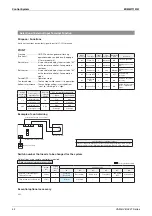
Number of units
controlled • Wiring length
The maximum total number of groups connected by centralized
transmission line can be up to 64 groups.
Max. length of centralized transmission line: Up to 1000m.
The maximum total number of groups connected by centralized
transmission line can be up to 64 groups.
Max. length of centralized transmission line: Up to 1000m.
Notes
[Unified ON / OFF controller]
Group number for centralized control needs to be set for each group.
Power supply is required.
[Schedule timer]
DC16V power supply is required for stand-alone use. Power can be
supplied from the printed circuit board of the main unit.
((X11A) in case of Heat Reclaim Ventilator Unit)
[Wiring adapter for electrical appendices]
For stand-alone use only. (The adapter can be incorporated into one of
the units.)
KRP2A62 for Heat Reclaim Ventilator Unit.
Direct duct connection is not possible when connected by a centralized
transmission line.
Group number for centralized control needs to be set for each group.
Power supply is required.
[Central remote controller]
To perform operations interlocking with air conditioners within the
same zone, field setting using remote controller (to set centralized zone
interlocking to "Yes") is always required.
Do not make this setting if there is no air conditioner (i.e., only Heat
Reclaim Ventilator Unit is present) in the same zone.
Page
36
37
Remote
controller
Summary of Contents for VAM Series
Page 2: ......
Page 4: ...EDMMT712101 2 Table of Contents 17 6 Precautions for Design and Installation 181 ...
Page 56: ...Control System EDMMT712101 54 VAM HVE HVLT Series C 3P343420 1E ...
Page 138: ...Installation Manual EDMMT712101 136 VAM HVE HVLT Series 3P607378 3C ...
Page 139: ...EDMMT712101 Installation Manual VAM HVE HVLT Series 137 3P607378 3C ...
Page 141: ...EDMMT712101 Installation Manual VAM HVE HVLT Series 139 C EM20A032 ...
Page 142: ...Installation Manual EDMMT712101 140 VAM HVE HVLT Series C EM20A032 ...
Page 143: ...EDMMT712101 Installation Manual VAM HVE HVLT Series 141 C EM20A032 ...
Page 147: ...EDMMT712101 Details of Optional Accessories VAM HVE HVLT Series 145 3P607378 3C ...
Page 148: ...Details of Optional Accessories EDMMT712101 146 VAM HVE HVLT Series 3P607378 3C ...
Page 149: ...EDMMT712101 Details of Optional Accessories VAM HVE HVLT Series 147 3P607378 3C ...
Page 150: ...Details of Optional Accessories EDMMT712101 148 VAM HVE HVLT Series 3P607378 3C ...
Page 151: ...EDMMT712101 Details of Optional Accessories VAM HVE HVLT Series 149 3P607378 3C ...
Page 152: ...Details of Optional Accessories EDMMT712101 150 VAM HVE HVLT Series 3P607378 3C ...
Page 155: ...EDMMT712101 Details of Optional Accessories VAM HVE HVLT Series 153 4P457318 1D ...
Page 156: ...Details of Optional Accessories EDMMT712101 154 VAM HVE HVLT Series 4P457318 1D ...
Page 157: ...EDMMT712101 Details of Optional Accessories VAM HVE HVLT Series 155 4P457318 1D ...
Page 158: ...Details of Optional Accessories EDMMT712101 156 VAM HVE HVLT Series 4P457318 1D ...
Page 159: ...EDMMT712101 Details of Optional Accessories VAM HVE HVLT Series 157 4P457318 1D ...
Page 184: ......
Page 185: ......
Page 186: ......
Page 187: ......


