EDMMT712101
Control System
VAM-HVE/HVLT Series
39
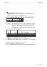
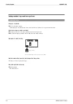
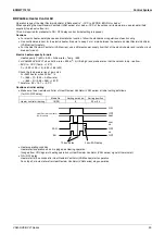
Extraction of operation/error indication (KRP1C18) [Heat Reclaim Ventilator Unit
→
Indicator (locally procured)]
Purpose
•
Functions
Extracts operation indication or error indication of one Heat Reclaim Ventilator Unit.
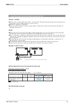
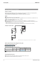
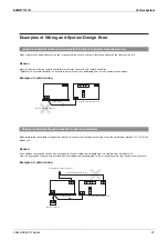
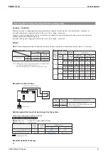
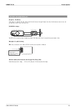
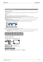
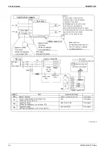
Example of control wiring
Extraction of operation indication
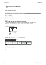
Extraction of error indication
Contact capacity
NO VOLTAGE A-CONTACT
240 VA or below
Heat Reclaim
Ventilator Unit
Power supply for indicators
X9A
X1
「
KRP1C18
」
X2
X3
X4
L
X9A
X1
「
KRP1C18
」
X2
X3
X4
L
P1 P2
P1 P2
Power supply for indicators
Heat Reclaim
Ventilator Unit
Contact capacity
NO VOLTAGE A-CONTACT
240 VA or below
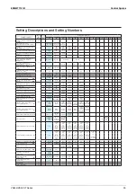
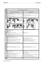
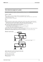
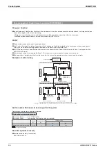
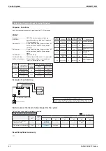
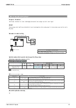
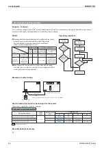
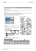
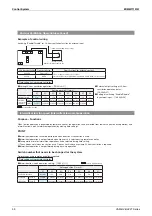
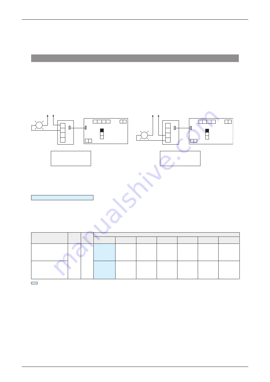
Switch number that needs to be changed for the system
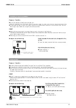
Field settings using remote controller is required.
Field settings using remote controller
Extraction of operation indication
Adapter for wiring output changeover setting (X1-2) .... [Remains at the factory default setting]
Extraction of error indication
Adapter for wiring output changeover setting (X3-4) .... [18(28)-9-02]
※
When using both operating indication and error indication together, please set to [18(28)-9-02].
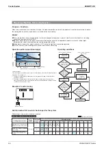
Mode
No.
Setting
switch
No.
Setting position
01
02
03
04
05
06
07
Adapter for wiring
Output changeover
selection (X3-4 terminals)
18 (28)
9
Humidification
output
(ordinary
humidification)
Abnormal
output
Fan operation
output
(Ultra high/
High/Low)
Fan operation
output
(Ultra high/
High)
Fan operation
output
(Ultra high)
Fan operation
output
(Ultra high/
High/Low)
Fan operation
output
(Ultra high/
High/Low)
Adapter for wiring
Output changeover
selection (X1-2 terminals)
Normal
operation
output
Normal
operation
output
Normal
operation
output
Normal
operation
output
Normal
operation
output
24-hour
ventilation
operation
and normal
operation
24-hour
ventilation
Operation
output
Factory default setting
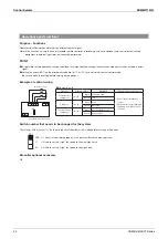
Essential optional accessory
Adapter for wiring: KRP1C18
Installation box for adapter: KRP1C18A90
Summary of Contents for VAM Series
Page 2: ......
Page 4: ...EDMMT712101 2 Table of Contents 17 6 Precautions for Design and Installation 181 ...
Page 56: ...Control System EDMMT712101 54 VAM HVE HVLT Series C 3P343420 1E ...
Page 138: ...Installation Manual EDMMT712101 136 VAM HVE HVLT Series 3P607378 3C ...
Page 139: ...EDMMT712101 Installation Manual VAM HVE HVLT Series 137 3P607378 3C ...
Page 141: ...EDMMT712101 Installation Manual VAM HVE HVLT Series 139 C EM20A032 ...
Page 142: ...Installation Manual EDMMT712101 140 VAM HVE HVLT Series C EM20A032 ...
Page 143: ...EDMMT712101 Installation Manual VAM HVE HVLT Series 141 C EM20A032 ...
Page 147: ...EDMMT712101 Details of Optional Accessories VAM HVE HVLT Series 145 3P607378 3C ...
Page 148: ...Details of Optional Accessories EDMMT712101 146 VAM HVE HVLT Series 3P607378 3C ...
Page 149: ...EDMMT712101 Details of Optional Accessories VAM HVE HVLT Series 147 3P607378 3C ...
Page 150: ...Details of Optional Accessories EDMMT712101 148 VAM HVE HVLT Series 3P607378 3C ...
Page 151: ...EDMMT712101 Details of Optional Accessories VAM HVE HVLT Series 149 3P607378 3C ...
Page 152: ...Details of Optional Accessories EDMMT712101 150 VAM HVE HVLT Series 3P607378 3C ...
Page 155: ...EDMMT712101 Details of Optional Accessories VAM HVE HVLT Series 153 4P457318 1D ...
Page 156: ...Details of Optional Accessories EDMMT712101 154 VAM HVE HVLT Series 4P457318 1D ...
Page 157: ...EDMMT712101 Details of Optional Accessories VAM HVE HVLT Series 155 4P457318 1D ...
Page 158: ...Details of Optional Accessories EDMMT712101 156 VAM HVE HVLT Series 4P457318 1D ...
Page 159: ...EDMMT712101 Details of Optional Accessories VAM HVE HVLT Series 157 4P457318 1D ...
Page 184: ......
Page 185: ......
Page 186: ......
Page 187: ......


