EDMMT712101
Control System
VAM-HVE/HVLT Series
53
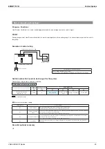
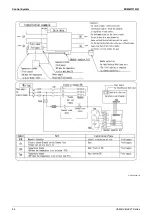
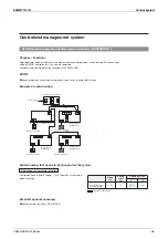
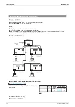
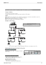
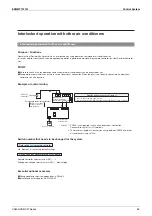
BRP4A50A: Heater Control Kit
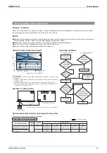
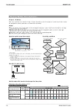
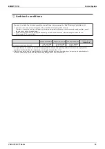
Operation range of the Heat Reclaim Ventilator (VAM series) is “ –15°C to 50°CDB 80% RH or below.”
When operating the Heat Reclaim Ventilator (VAM series) at or below –10°C of the outdoor air temperature, use preheater (field
supplied) to preheat outdoor air.
This kit is required for preheater to ON / OFF delay control. (Initial setting is required.)
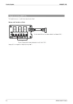
Cautions
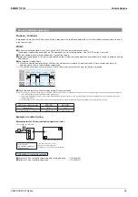
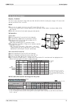
For electric heater, safety devices and installation location, follow the standards or regulations of each country.
Use nonflammable duct for the electric heater. Be sure to keep 2 m or more between the heater and Heat Reclaim Ventilator
(VAM series) for safety.
For the Heat Reclaim Ventilator (VAM series), use a different power supply from that of the electric heater and install a circuit
breaker for each.
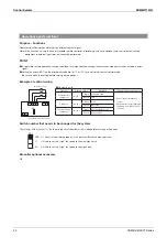
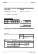
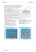
Electric heater capacity formula
Heat capacity P (kW) = 0.29
Airflow rate
Temp. / 860
For VAM500HVE/HVLT when Airflow rate = 500 m
3
/ h (Ultra-high) and preheater so that the outdoor temp. rise from
–20°C to –10°C (Temp. = 10°C)
P = (0.29
500
10) / 860 = 1.68 (kW)
Check the temperature rise at low notch.
For 2kW heater, when 300 m
3
/ h
T = (860
P) / (0.29
Airflow rate)
= (860
2) / (0.29
300) = 19.7°C
Therefore – 20 + 19.7 = –0.3°C
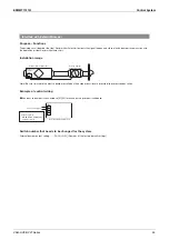
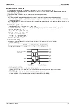
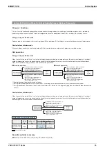
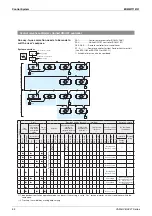
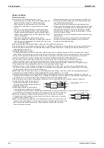
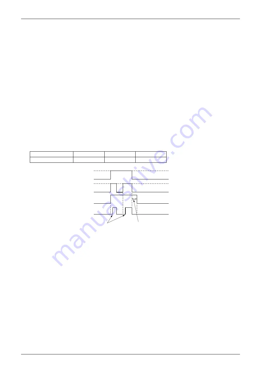
Cautions at initial setting
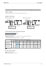
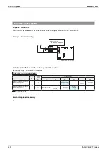
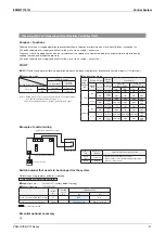
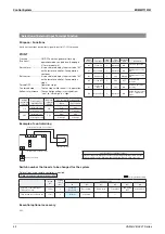
Make sure to set remote controller of Heat Reclaim Ventilator (VAM series) at initial setting as follows :
(for ON / OFF delay)
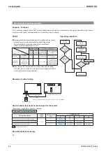
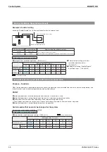
Heater operating condition
Heater starts operation when it is judged as Heating operation.
(Judged from
VRV
signal of heating operation or Heat Reclaim Ventilator (VAM series) signal of thermostat.)
ON / OFF delay
Heater starts 10 seconds after Heat Reclaim Ventilator (VAM series) starts operation.
Fan stops 3 minutes later after Heat Reclaim Ventilator (VAM series) stops operation.
Mode No.
Setting switch no.
Setting position
Heater control kit setting
19 (29)
8
03 or 04
ON
OFF
FAN
EH
10 sec. delay
3 min. FAN delay
heat
cool
on
OFF
on
OFF
Heat Reclaim Ventilator
(VAM series)
Summary of Contents for VAM Series
Page 2: ......
Page 4: ...EDMMT712101 2 Table of Contents 17 6 Precautions for Design and Installation 181 ...
Page 56: ...Control System EDMMT712101 54 VAM HVE HVLT Series C 3P343420 1E ...
Page 138: ...Installation Manual EDMMT712101 136 VAM HVE HVLT Series 3P607378 3C ...
Page 139: ...EDMMT712101 Installation Manual VAM HVE HVLT Series 137 3P607378 3C ...
Page 141: ...EDMMT712101 Installation Manual VAM HVE HVLT Series 139 C EM20A032 ...
Page 142: ...Installation Manual EDMMT712101 140 VAM HVE HVLT Series C EM20A032 ...
Page 143: ...EDMMT712101 Installation Manual VAM HVE HVLT Series 141 C EM20A032 ...
Page 147: ...EDMMT712101 Details of Optional Accessories VAM HVE HVLT Series 145 3P607378 3C ...
Page 148: ...Details of Optional Accessories EDMMT712101 146 VAM HVE HVLT Series 3P607378 3C ...
Page 149: ...EDMMT712101 Details of Optional Accessories VAM HVE HVLT Series 147 3P607378 3C ...
Page 150: ...Details of Optional Accessories EDMMT712101 148 VAM HVE HVLT Series 3P607378 3C ...
Page 151: ...EDMMT712101 Details of Optional Accessories VAM HVE HVLT Series 149 3P607378 3C ...
Page 152: ...Details of Optional Accessories EDMMT712101 150 VAM HVE HVLT Series 3P607378 3C ...
Page 155: ...EDMMT712101 Details of Optional Accessories VAM HVE HVLT Series 153 4P457318 1D ...
Page 156: ...Details of Optional Accessories EDMMT712101 154 VAM HVE HVLT Series 4P457318 1D ...
Page 157: ...EDMMT712101 Details of Optional Accessories VAM HVE HVLT Series 155 4P457318 1D ...
Page 158: ...Details of Optional Accessories EDMMT712101 156 VAM HVE HVLT Series 4P457318 1D ...
Page 159: ...EDMMT712101 Details of Optional Accessories VAM HVE HVLT Series 157 4P457318 1D ...
Page 184: ......
Page 185: ......
Page 186: ......
Page 187: ......


