
EDMMT712101
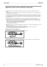
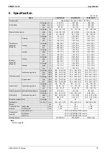
Control System
VAM-HVE/HVLT Series
69
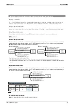
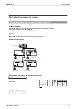
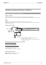
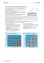
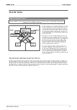
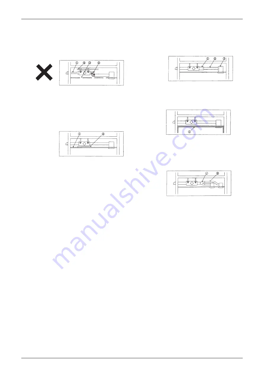
Reduction of noise from equipment behind the
ceiling and air passage
1. If noise reduction measures are necessary for large
equipment (650 m
3
/h or more), avoid providing the following
constructions as much as possible. (See Fig. 1)
①
Do not narrow down the duct diameter too much.
(Example:
I
250
o
I
150,
I
200
o
I
100)
②
Do not bend too much using aluminum bellows, etc.
(In particular, bending immediately after the main unit
outlet)
③
Do not open the ceiling board unnecessarily.
④
$ONOTHANGITONACEILINGCOMPONENTWITHINSUFÚCIENT
strength.
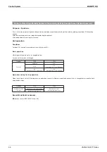
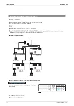
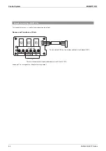
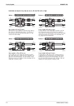
2. The following countermeasures are available. (See Fig. 2)
①
Use a ceiling component with high sound insulation
(high transmission loss).
< Caution>
In particular, some low-frequency components provide
little sound insulation.
②
Add sound insulation materials around the bottom of
the sound source.
< Caution>
Sound insulation sheets need to cover the whole
equipment, but some equipment may not be covered due
TOTHEINÛUENCEOFHEATDISSIPATION
Fig. 1
Fig. 2
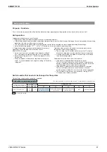
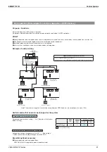
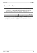
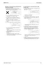
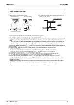
Countermeasures for noise from the air outlet
(suction port)
1. For ceiling mounted duct type, using the following separately
sold items is recommended.
(See Fig. 3)
①
Silencer box
②
Flexible duct
③
Silent supply/exhaust grille
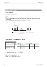
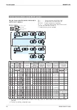
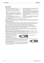
)FTHEMEASURESINABOVEAREINSUFÚCIENTORIFTHECEILING
mounted cassette type is used, the following methods are
available. (See Fig. 4 and 5)
①
Use materials with high sound absorption for the room
interior materials.
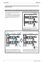
&ORTHECEILINGMOUNTEDDUCTTYPEIFTHEAIRÛOWNOISEIS
generated from the air outlet (suction port) itself, and if
THELENGTHANDÛOWVELOCITYARETHESAMETHEFOLLOWING
METHODSAREAVAILABLEASTHESMALLDIAMETERÛEXIBLEDUCT
has a higher sound absorption effect.
①
Branch duct (divide the amount of blown air and reduce the
AIRÛOWVELOCITYATTHEOUTLETSUCTIONPORT
②
Flexible duct
4. Providing a sound source in the corner of the room is an
effective noise reduction measure for the center of the room,
but not effective when people are present in the corner.
Fig. 3
Fig. 4
Fig. 5
Summary of Contents for VAM Series
Page 2: ......
Page 4: ...EDMMT712101 2 Table of Contents 17 6 Precautions for Design and Installation 181 ...
Page 56: ...Control System EDMMT712101 54 VAM HVE HVLT Series C 3P343420 1E ...
Page 138: ...Installation Manual EDMMT712101 136 VAM HVE HVLT Series 3P607378 3C ...
Page 139: ...EDMMT712101 Installation Manual VAM HVE HVLT Series 137 3P607378 3C ...
Page 141: ...EDMMT712101 Installation Manual VAM HVE HVLT Series 139 C EM20A032 ...
Page 142: ...Installation Manual EDMMT712101 140 VAM HVE HVLT Series C EM20A032 ...
Page 143: ...EDMMT712101 Installation Manual VAM HVE HVLT Series 141 C EM20A032 ...
Page 147: ...EDMMT712101 Details of Optional Accessories VAM HVE HVLT Series 145 3P607378 3C ...
Page 148: ...Details of Optional Accessories EDMMT712101 146 VAM HVE HVLT Series 3P607378 3C ...
Page 149: ...EDMMT712101 Details of Optional Accessories VAM HVE HVLT Series 147 3P607378 3C ...
Page 150: ...Details of Optional Accessories EDMMT712101 148 VAM HVE HVLT Series 3P607378 3C ...
Page 151: ...EDMMT712101 Details of Optional Accessories VAM HVE HVLT Series 149 3P607378 3C ...
Page 152: ...Details of Optional Accessories EDMMT712101 150 VAM HVE HVLT Series 3P607378 3C ...
Page 155: ...EDMMT712101 Details of Optional Accessories VAM HVE HVLT Series 153 4P457318 1D ...
Page 156: ...Details of Optional Accessories EDMMT712101 154 VAM HVE HVLT Series 4P457318 1D ...
Page 157: ...EDMMT712101 Details of Optional Accessories VAM HVE HVLT Series 155 4P457318 1D ...
Page 158: ...Details of Optional Accessories EDMMT712101 156 VAM HVE HVLT Series 4P457318 1D ...
Page 159: ...EDMMT712101 Details of Optional Accessories VAM HVE HVLT Series 157 4P457318 1D ...
Page 184: ......
Page 185: ......
Page 186: ......
Page 187: ......


