
Control System
EDMMT712101
70
VAM-HVE/HVLT Series
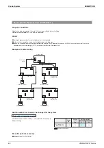
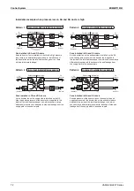
Branch duct
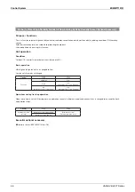
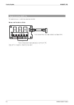
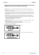
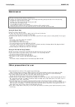
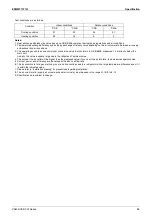
Avoid using OA/EA branch duct for multiple Heat Reclaim Ventilator units as much as possible, and instead install ducts for each main unit. (Fig. 1)
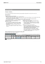
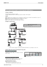
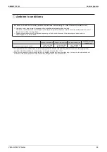
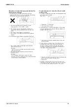
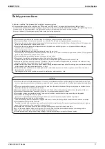
)FMULTIPLE/!%!BRANCHDUCTSAREUSEDAIRÛOWSHOWNIN
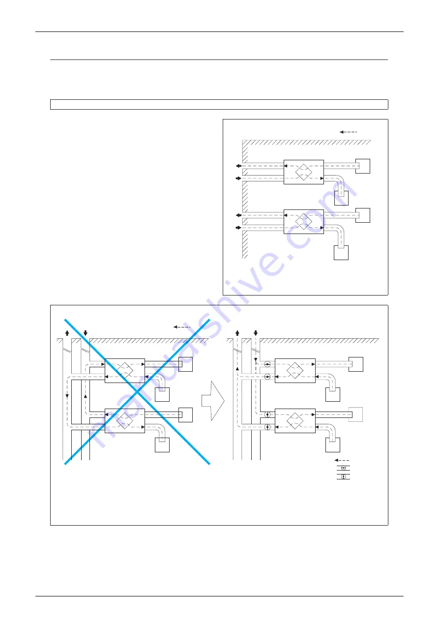
Fig. 2 will occur, which makes it impossible for the normal air
ÛOWTOBEMAINTAINED
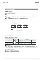
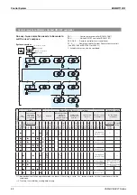
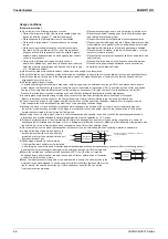
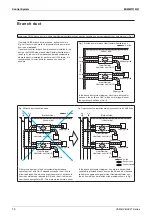
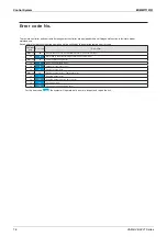
)FANELECTRICSHUTTERFORBACKÛOWPREVENTIONISINSTALLEDINTHE
duct on the OA/EA side of each Heat Reclaim Ventilator unit
(see Fig. 3), the cost will increase considerably compared to
where the duct is installed for each main unit. Therefore, it is
recommended to install ducts for each unit as much as
possible.
Fig. 1 Provide ducts for each Heat Reclaim Ventilator unit.
In the above duct system diagram, if ducts are installed for
EACHUNITTHEAIRÛOWIN5NITWILLBENORMALREGARDLESSOF
the operating conditions of Unit 2.
Fig. 2 Branch duct cannot be used.
&IG)NSTALLABACKÛOWPREVENTIONDAMPERONEACHDUCTONTHE/!%!SIDE
If there is no damper in the duct system diagram above,
OPERATING5NITWITH5NITSTOPPEDWILLCAUSETHEAIRÛOWTO
follow the broken line, which causes the amount of air taken in
from the outside to be reduced for OA, and the air to blow out
FROMTHEEXHAUSTGRILLEFOR%!4HISPREVENTSTHENORMALAIRÛOW
)NTHEABOVEDUCTSYSTEMDIAGRAMIFANELECTRICSHUTTERÚELD
supplied) is provided at each duct on the OA and EA sides and
linked to the operation signal of Heat Reclaim Ventilator unit,
THEAIRÛOWWILLBENORMALWITHOUTTHEPROBLEMSSHOWNIN&IG
(Indoor side)
: Air flow
Exhaust grille
Heat Reclaim
Ventilator unit (Unit 1)
Heat Reclaim
Ventilator unit (Unit 2)
Supply grille
Exhaust grille
Supply grille
(Outdoor side)
EA
OA
EA
OA
OA
EA
EA
OA
SA
RA
SA
RA
EA
OA
OA
EA
SA
RA
EA
OA
: Air flow
(Outdoor side)
(Indoor side)
Supply grille
Supply grille
Exhaust grille
Heat Reclaim
Ventilator unit (Unit 1)
Exhaust grille
Heat Reclaim
Ventilator unit (Unit 2)
(Outdoor side)
(Indoor side)
Supply grille
Supply grille
Exhaust grille
Heat Reclaim
Ventilator unit (Unit 1)
Exhaust grille
Heat Reclaim
Ventilator unit (Unit 2)
: Air flow
: Shutter open
: Shutter closed
Summary of Contents for VAM Series
Page 2: ......
Page 4: ...EDMMT712101 2 Table of Contents 17 6 Precautions for Design and Installation 181 ...
Page 56: ...Control System EDMMT712101 54 VAM HVE HVLT Series C 3P343420 1E ...
Page 138: ...Installation Manual EDMMT712101 136 VAM HVE HVLT Series 3P607378 3C ...
Page 139: ...EDMMT712101 Installation Manual VAM HVE HVLT Series 137 3P607378 3C ...
Page 141: ...EDMMT712101 Installation Manual VAM HVE HVLT Series 139 C EM20A032 ...
Page 142: ...Installation Manual EDMMT712101 140 VAM HVE HVLT Series C EM20A032 ...
Page 143: ...EDMMT712101 Installation Manual VAM HVE HVLT Series 141 C EM20A032 ...
Page 147: ...EDMMT712101 Details of Optional Accessories VAM HVE HVLT Series 145 3P607378 3C ...
Page 148: ...Details of Optional Accessories EDMMT712101 146 VAM HVE HVLT Series 3P607378 3C ...
Page 149: ...EDMMT712101 Details of Optional Accessories VAM HVE HVLT Series 147 3P607378 3C ...
Page 150: ...Details of Optional Accessories EDMMT712101 148 VAM HVE HVLT Series 3P607378 3C ...
Page 151: ...EDMMT712101 Details of Optional Accessories VAM HVE HVLT Series 149 3P607378 3C ...
Page 152: ...Details of Optional Accessories EDMMT712101 150 VAM HVE HVLT Series 3P607378 3C ...
Page 155: ...EDMMT712101 Details of Optional Accessories VAM HVE HVLT Series 153 4P457318 1D ...
Page 156: ...Details of Optional Accessories EDMMT712101 154 VAM HVE HVLT Series 4P457318 1D ...
Page 157: ...EDMMT712101 Details of Optional Accessories VAM HVE HVLT Series 155 4P457318 1D ...
Page 158: ...Details of Optional Accessories EDMMT712101 156 VAM HVE HVLT Series 4P457318 1D ...
Page 159: ...EDMMT712101 Details of Optional Accessories VAM HVE HVLT Series 157 4P457318 1D ...
Page 184: ......
Page 185: ......
Page 186: ......
Page 187: ......


