

EDMMT712101
Control System
VAM-HVE/HVLT Series
71
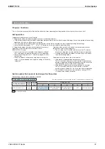
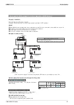
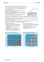
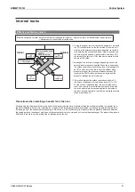
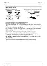
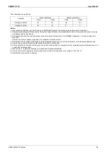
Internal leaks
Effective ventilation volume
"Effective ventilation volume": Amount of outside air supplied (air volume) - Amount of return air leaked inside the equipment
※
= Net amount of fresh outside air introduced
Leakage of return air
※
10% or less
RA
(Return air)
OA
(Outside air)
Effective ventilation volume
90%
or more
※
SA
(Supply air)
EA
(Exhaust air)
※
For the leakage of return air inside the equipment, measure
the CO
2
concentration on the indoor side of the main unit
with the rated external static pressure applied, so that the
ratio between the outdoor and indoor sides is even during
the ultra-high tap operation, and calculate how much CO
2
contained in the return air (RA) side has transferred to the
supply air (SA) side.
※
Leakage of the return air changes depending on how the
external static pressure is applied. When the ratio between
the outdoor and indoor sides is evenly set, the leakage will
be 10% or less, but when the ratio of the outdoor static
pressure is higher, the pressure difference between SA
(supply air) and RA (return air) becomes large, and the
amount of leakage tends to increase.
※
If the ratio between the outdoor and indoor sides is 2:1,
the amount of leakage will increase by about 5% to 15%.
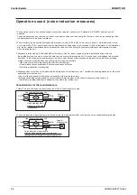
For the outdoor installation type, the duct outside of the
room is not required, so the calculation is performed with
the rated external static pressure applied to the inside of
the room instead. Therefore, the effective ventilation volume
may be less than 90%.
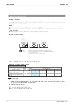
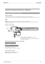
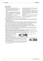
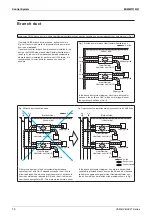
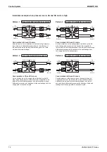
Precautions when installing a booster fan in the duct
For large models, the pressure loss in the ducts will be larger than the static pressure outside the standard machine. If a booster fan or
the like is installed in such ducts, install the fan in the duct with the largest pressure loss whether it is the supply path [OA (outside air),
SA (supply air)] or the exhaust path [exhaust path RA (return air), EA (exhaust air)] to make sure that the pressure difference between
the supply path and the exhaust path does not become excessive in the main body of the total heat exchanger. The greater the pressure
difference in the main unit, the greater the air leakage inside the unit.
Indoor
Outdoor
Summary of Contents for VAM Series
Page 2: ......
Page 4: ...EDMMT712101 2 Table of Contents 17 6 Precautions for Design and Installation 181 ...
Page 56: ...Control System EDMMT712101 54 VAM HVE HVLT Series C 3P343420 1E ...
Page 138: ...Installation Manual EDMMT712101 136 VAM HVE HVLT Series 3P607378 3C ...
Page 139: ...EDMMT712101 Installation Manual VAM HVE HVLT Series 137 3P607378 3C ...
Page 141: ...EDMMT712101 Installation Manual VAM HVE HVLT Series 139 C EM20A032 ...
Page 142: ...Installation Manual EDMMT712101 140 VAM HVE HVLT Series C EM20A032 ...
Page 143: ...EDMMT712101 Installation Manual VAM HVE HVLT Series 141 C EM20A032 ...
Page 147: ...EDMMT712101 Details of Optional Accessories VAM HVE HVLT Series 145 3P607378 3C ...
Page 148: ...Details of Optional Accessories EDMMT712101 146 VAM HVE HVLT Series 3P607378 3C ...
Page 149: ...EDMMT712101 Details of Optional Accessories VAM HVE HVLT Series 147 3P607378 3C ...
Page 150: ...Details of Optional Accessories EDMMT712101 148 VAM HVE HVLT Series 3P607378 3C ...
Page 151: ...EDMMT712101 Details of Optional Accessories VAM HVE HVLT Series 149 3P607378 3C ...
Page 152: ...Details of Optional Accessories EDMMT712101 150 VAM HVE HVLT Series 3P607378 3C ...
Page 155: ...EDMMT712101 Details of Optional Accessories VAM HVE HVLT Series 153 4P457318 1D ...
Page 156: ...Details of Optional Accessories EDMMT712101 154 VAM HVE HVLT Series 4P457318 1D ...
Page 157: ...EDMMT712101 Details of Optional Accessories VAM HVE HVLT Series 155 4P457318 1D ...
Page 158: ...Details of Optional Accessories EDMMT712101 156 VAM HVE HVLT Series 4P457318 1D ...
Page 159: ...EDMMT712101 Details of Optional Accessories VAM HVE HVLT Series 157 4P457318 1D ...
Page 184: ......
Page 185: ......
Page 186: ......
Page 187: ......


