Control System
EDMMT712101
72
VAM-HVE/HVLT Series
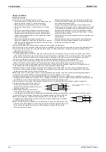
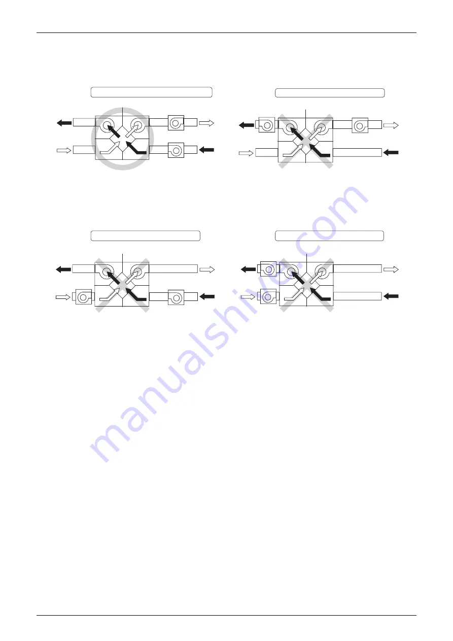
Pattern 1
Recommended installation example
Fan installed in SA and RA ducts
As each booster fan is installed in a duct with a high pressure
LOSSTHEREISNODIFFERENTIALPRESSUREDUETOTHEINÛUENCEOF
the booster fan inside the total heat exchange unit, so there
will be almost zero leakage.
Pattern 2
Incorrect installation example
Fans installed in OA and RA ducts
As the booster fan on the supply side is installed on the OA
side, the positive pressure of the booster fan is applied to the
inside of the total heat exchanger unit, which causes a large
differential pressure with the exhaust side and leakage from the
supply path to the exhaust path.
EA
(Exhaust air)
SA
(Supply air)
Outdoor side Indoor side
OA
(Outside air)
RA
(Return air)
EA
(Exhaust air)
SA
(Supply air)
Outdoor side Indoor side
OA
(Outside air)
RA
(Return air)
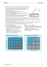
Pattern 3
Incorrect installation example
Fans installed in SA and EA ducts
As the booster fan on the exhaust side is installed on the EA
side, the negative pressure of the booster fan is applied to
the inside of the total heat exchanger unit, which causes a large
differential pressure with the exhaust side and leakage from
the supply path to the exhaust path.
Pattern 4
Incorrect installation example
Fans installed in OA and EA ducts
Positive pressure of the booster fan on the supply side and
negative pressure of the booster fan on the exhaust side are
applied to the inside of the total heat exchanger unit, which
causes a large differential pressure with the exhaust side and
leakage from the supply path to the exhaust path.
EA
(Exhaust air)
SA
(Supply air)
Outdoor side Indoor side
OA
(Outside air)
RA
(Return air)
EA
(Exhaust air)
SA
(Supply air)
Outdoor side Indoor side
OA
(Outside air)
RA
(Return air)
Installation example when pressure loss in SA and RA ducts is high
Summary of Contents for VAM Series
Page 2: ......
Page 4: ...EDMMT712101 2 Table of Contents 17 6 Precautions for Design and Installation 181 ...
Page 56: ...Control System EDMMT712101 54 VAM HVE HVLT Series C 3P343420 1E ...
Page 138: ...Installation Manual EDMMT712101 136 VAM HVE HVLT Series 3P607378 3C ...
Page 139: ...EDMMT712101 Installation Manual VAM HVE HVLT Series 137 3P607378 3C ...
Page 141: ...EDMMT712101 Installation Manual VAM HVE HVLT Series 139 C EM20A032 ...
Page 142: ...Installation Manual EDMMT712101 140 VAM HVE HVLT Series C EM20A032 ...
Page 143: ...EDMMT712101 Installation Manual VAM HVE HVLT Series 141 C EM20A032 ...
Page 147: ...EDMMT712101 Details of Optional Accessories VAM HVE HVLT Series 145 3P607378 3C ...
Page 148: ...Details of Optional Accessories EDMMT712101 146 VAM HVE HVLT Series 3P607378 3C ...
Page 149: ...EDMMT712101 Details of Optional Accessories VAM HVE HVLT Series 147 3P607378 3C ...
Page 150: ...Details of Optional Accessories EDMMT712101 148 VAM HVE HVLT Series 3P607378 3C ...
Page 151: ...EDMMT712101 Details of Optional Accessories VAM HVE HVLT Series 149 3P607378 3C ...
Page 152: ...Details of Optional Accessories EDMMT712101 150 VAM HVE HVLT Series 3P607378 3C ...
Page 155: ...EDMMT712101 Details of Optional Accessories VAM HVE HVLT Series 153 4P457318 1D ...
Page 156: ...Details of Optional Accessories EDMMT712101 154 VAM HVE HVLT Series 4P457318 1D ...
Page 157: ...EDMMT712101 Details of Optional Accessories VAM HVE HVLT Series 155 4P457318 1D ...
Page 158: ...Details of Optional Accessories EDMMT712101 156 VAM HVE HVLT Series 4P457318 1D ...
Page 159: ...EDMMT712101 Details of Optional Accessories VAM HVE HVLT Series 157 4P457318 1D ...
Page 184: ......
Page 185: ......
Page 186: ......
Page 187: ......

