


EDMMT712101
Installation Manual
VAM-HVE/HVLT Series
123
13.Installation Manual
13.1 Installation Manual
3P645058-1
1
English
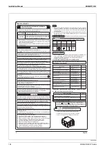
Notes
y
Give the user adequate instructions concerning the unit’s proper operation
(especially cleaning air filter and heat exchange elements and operating the
unit) by letting the customer operate the air conditioner while referring to the
operation manual.
y
Do not use the unit in a place where the air contains high levels of salt, such as
that near the ocean, or where voltage fluctuates greatly, such as in factories and
vehicles or vessels.
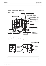
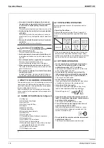
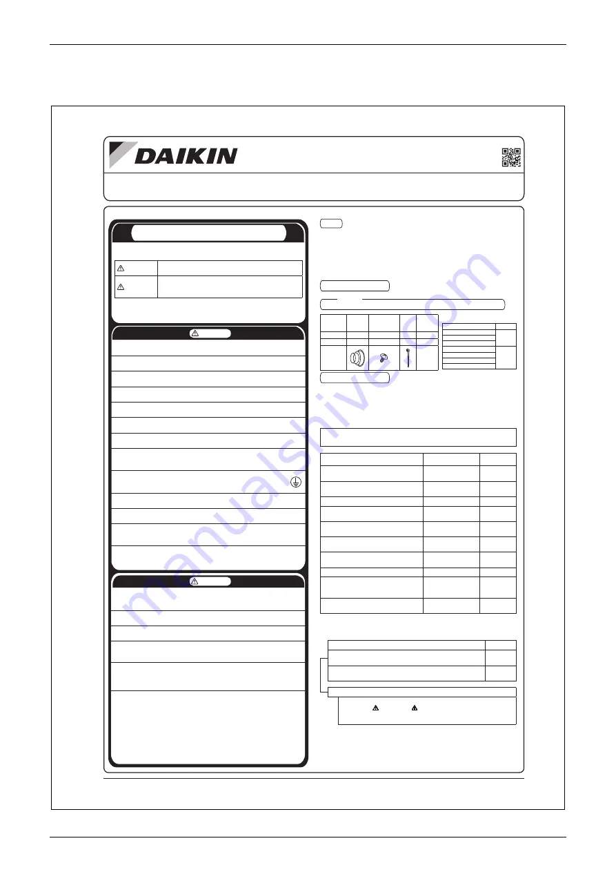
Checking
accessories
Check that the accessories in the table below are included with your unit.
Do not dispose of any parts necessary for installation until the installation is completed.
<Note>
Name
①
Duct
connector
②
Screw for mounting
duct connecting
screws
③
Clamp
(Others)
Supplied Quantity
4 pcs.
24 pcs.
8 pcs.
1 copy each
Usage Quantity
4 pcs.
Right table
7 pcs.
1 copy each
Shape
t
Installation
Manual
t
Operation
Manual
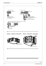
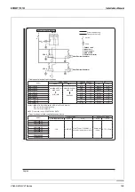
②
For mounting duct connector
Screw quantity
Number of
screws
Model names
Number
VAM150HVE
16pcs.
VAM250HVE
VAM350HVE
VAM500HVE
24pcs.
VAM650HVE
VAM800HVE
VAM1000HVE
3P645058-1
VAM150HV
E
·
VAM250HV
E
·
VAM350HV
E
·
VAM500HV
E
·
VAM650HV
E
·
VAM800HV
E
·
VAM1000HV
E
·
VAM1500HV
E
·
VAM2000HV
E
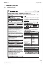
INSTALLATION
MANUAL
-
(Ceiling
Mounted
Duct
Type)
Be
sure
to
read
this
installation
manual
before
commencing
installation
and
perform
installation
w
ork
according
to
the
manual.
Optional
accessories
y
When installing this unit, prepare all components required for installation, such
as the optional remote controller, outdoor hood, and intake/exhaust grill.
For selection of optional accessories, refer to the general catalog (for
designers/construction personnel).
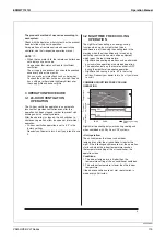
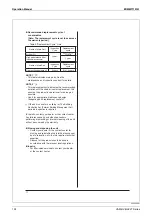
(1)
Items
to
be
checked
after
completion
of
installation
w
ork
Pay
extra
attention
to
the
contents
listed
belo
w
and
check
again
after
the
installation
w
ork
is
completed.
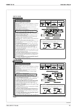
Items to be checked
If not correctly done, what is likely
to occur
Check column
r
o
,e
ta
r
bi
v
,p
o
r
d
y
a
m
ti
n
u
e
h
T
?
yl
m
r fi
d
el
la
ts
ni
ti
n
u
ni
a
m
e
ht
s
I
make noise
Is the outdoor duct installed to outside with a downward slope?
Condensate water may drip, electric
shock or fi re may occur
pi
r
d
y
a
m
r
et
a
w
e
ta
s
n
e
d
n
o
C
?
d
et
al
u
s
ni
y
ll
uf
t
c
u
d
e
ht
s
I
Does the power supply voltage correspond to that shown on
the nameplate?
The unit may malfunction, or the
components may burn out
Are all wirings correct?
The unit may malfunction, or the
components may burn out
n
i r
u
c
c
o
y
a
m
e
r fi
r
o
k
c
o
h
s
ci
rt
c
el
E
?
d
e
d
n
u
o
r
g
yl
ef
a
s
ti
n
u
e
ht
s
I
the event of electric leakage
Are wiring sizes according to the specifi cations?
The unit may malfunction, or the
components may burn out
r
u
c
c
o
y
a
m
e
r fi
r
o
k
c
o
h
s
ci
rt
c
el
E
?
e
s
o
ol
t
o
n
s
n
oi
tc
e
n
n
o
c
g
ni
ri
w
e
r
A
Make sure that the insulation resistance value is 1M
Ω
or greater.
y
Use a 500V mega tester for insulation measurement.
y
Do not use a mega tester for low voltage circuits.
Electric shock or fi re may occur
e
si
o
n
r
o
n
oi
ta
lit
n
e
v
tn
ei
c
fif
u
s
nI
?t
el
ni
r
o
te
lt
u
o
ri
a
e
ht
g
ni
k
c
ol
b
g
ni
ht
e
m
o
s
sI
may occur
Please
check
all
items
listed
in
the
“Safety
Precautions”
on
the
left
once
again.
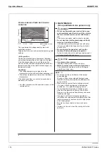
(2)
Items
to
be
checked
at
the
time
of
delivery
k
c
e
h
C
d
e
k
c
e
h
c
e
b
o
t
s
m
e
t
I
Did you explain about the operations while showing the
operation manual to your customer?
Did you hand the operation manual, installation manual, and
warranty card over to your customer?
Points for explanation about operations
- In addition to the general operations, you need to explain the items
marked with WARNING or
CAUTION in the operation manual since
they are items that could lead to physical injury or property damage. You
also need to ask your customer to read them carefully.
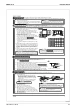
Please
read
these
“Safety
Precautions”
carefully
and
install
the
unit
properly.
WARNING
Ask your local dealer or qualifi ed personnel to carry out installation work.
Do not attempt to install the unit by yourself. Improper installation may result in water leakage, electric shock, or fi re.
Installation should be carried out following the installation manual, and no changes should be made to the unit.
Improper installation may result in water leakage, electric shock, or fi re.
Be sure to use only the specifi ed parts and accessories for installation work.
Failure to use the specifi ed parts may result in the unit falling over, water leakage, electric shock, fi re, etc.
Install the unit according to this installation manual on a foundation that can withstand its mass.
Insuffi cient strength or improper installation may result in the unit falling over and causing injury.
Carry out the specifi ed installation work in consideration of strong winds such as typhoons or earthquakes.
Improper installation may result in an accident due to causes such as the unit falling over.
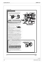
Do not allow exhaust air to enter the outside air intake vent directly.
This may cause the air of the room to become contaminated, resulting in harm to the health.
Locate the outside air intake vent so that it does not take in exhaust air which contains combustion gas, etc.
Incorrect installation may cause a loss of oxygen in the room, which may lead to an accident.
Electrical work should be done by a qualifi ed electrician according to the installation instructions. Be sure to use
a dedicated circuit and do not add wires. Insuffi cient power supply circuit capacity or improper construction may
cause electric shock or fi re.
Earth the unit.
Do not connect the earth wire to gas pipes, water pipes, lightning rods, or telephone earth wires.
Incomplete earthing may cause electric shock or fi re.
Install a circuit breaker.
Failure to install a circuit breaker may result in electric shock or fi re.
Disconnect the power supply before touching any electric parts.
Touching a live part may result in electric shock.
Make sure that all wiring is securely connected to the respective terminal, using the specifi ed wires and ensuring
that external forces do not act on the terminal.
Incomplete connection or fi xing may cause overheating of the terminal or fi re.
When connecting the power supply wiring, remote controller wiring, or transmission wiring, form the wiring orderly
so that the electrical component box lid or other structures can be securely attached.
If the lid is not attached completely, electric shock or fi re may result.
y
The precautions described in this document are divided into the following two types.
Be sure to follow all the important safety precautions below.
WARNING
Indicates a potentially hazardous situation that could result in death
or severe injury if not avoided.
CAUTION
Indicates a potentially hazardous situation that, if not avoided, may
result in personal injury or property damage, which may lead to
severe consequences depending on the circumstances.
y
After the installation is completed, perform a test run and check that the unit operates properly. Give the
user adequate instructions concerning the use and cleaning of the unit according to the Operation Manual.
Inform the user to keep this manual and the Operation Manual together in a handy place for future reference.
Install the main unit and its power supply wiring, transmission wiring, and remote controller wiring at least 1
meter away from televisions or radios. This is to prevent image interference or noise.
(Depending on the radio waves, a distance of 1 meter may not be suffi cient to eliminate the noise.)
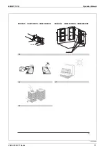
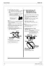
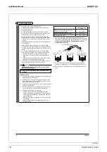
Install the outdoor ducts towards outside with a downward slope to prevent entry of rainwater.
If this is not done completely, water may enter into indoor spaces and damage furniture, etc.
Insulate the outdoor ducts to prevent condensation.
If this is not done completely, water may enter into indoor spaces and damage furniture, etc.
Insulate the duct and the wall electrically when a metal duct is passed through a metal lattice, wire lattice, or
metal lining of a wooden structure.
Failure to do so may cause electric shock or fi re.
Ensure that the temperature and humidity of the installation site are within the operating temperature/humidity
range of the unit.
Do not install the unit in a low-temperature chamber such as a refrigerator or at a heated swimming pool.
Failure to do so may cause electric shock or fi re.
Do not install the unit in places such as the following:
1. Place subjected to high temperature or direct fl ame. Overheat or fi re may result.
2. Where there is mist of oil, oil spray, or vapor, for example, a kitchen. Fire may result.
3. Where toxic gas from acid, alkaline, organic solvents or coating, or corrosive gas is produced, for example,
a machinery or chemical plant. Gas poisoning or fi re may result.
4. Place subject to high humidity. Electric shock or electrical leakage may result.
5. Where there is machinery that emits electromagnetic waves.
Electromagnetic waves may disturb the control system and cause malfunction of the unit.
6. Where fl ammable gases may leak, where carbon fi ber or ignitable dust is suspended in the air or where
volatile fl ammables, such as thinner or gasoline, are handled.
If the gas should leak and remain around the unit, it may cause ignition.
CAUTION
VAM150-1000HV
E
Summary of Contents for VAM Series
Page 2: ......
Page 4: ...EDMMT712101 2 Table of Contents 17 6 Precautions for Design and Installation 181 ...
Page 56: ...Control System EDMMT712101 54 VAM HVE HVLT Series C 3P343420 1E ...
Page 138: ...Installation Manual EDMMT712101 136 VAM HVE HVLT Series 3P607378 3C ...
Page 139: ...EDMMT712101 Installation Manual VAM HVE HVLT Series 137 3P607378 3C ...
Page 141: ...EDMMT712101 Installation Manual VAM HVE HVLT Series 139 C EM20A032 ...
Page 142: ...Installation Manual EDMMT712101 140 VAM HVE HVLT Series C EM20A032 ...
Page 143: ...EDMMT712101 Installation Manual VAM HVE HVLT Series 141 C EM20A032 ...
Page 147: ...EDMMT712101 Details of Optional Accessories VAM HVE HVLT Series 145 3P607378 3C ...
Page 148: ...Details of Optional Accessories EDMMT712101 146 VAM HVE HVLT Series 3P607378 3C ...
Page 149: ...EDMMT712101 Details of Optional Accessories VAM HVE HVLT Series 147 3P607378 3C ...
Page 150: ...Details of Optional Accessories EDMMT712101 148 VAM HVE HVLT Series 3P607378 3C ...
Page 151: ...EDMMT712101 Details of Optional Accessories VAM HVE HVLT Series 149 3P607378 3C ...
Page 152: ...Details of Optional Accessories EDMMT712101 150 VAM HVE HVLT Series 3P607378 3C ...
Page 155: ...EDMMT712101 Details of Optional Accessories VAM HVE HVLT Series 153 4P457318 1D ...
Page 156: ...Details of Optional Accessories EDMMT712101 154 VAM HVE HVLT Series 4P457318 1D ...
Page 157: ...EDMMT712101 Details of Optional Accessories VAM HVE HVLT Series 155 4P457318 1D ...
Page 158: ...Details of Optional Accessories EDMMT712101 156 VAM HVE HVLT Series 4P457318 1D ...
Page 159: ...EDMMT712101 Details of Optional Accessories VAM HVE HVLT Series 157 4P457318 1D ...
Page 184: ......
Page 185: ......
Page 186: ......
Page 187: ......


