Si71-812
Operation
Opration
21
Remote Controller and Changeover Switch:
Name and Function of Each Switch and Display
Only the items marked with an asterisk (
∗
mark) are explanation relating to the functions and display of
the unit. Unmarked items are functions of the combined air conditioners. When using buttons for
functions which are not available (buttons which are not described in the text) will cause “NOT
AVAILABLE” to be displayed.
Contact your dealer for more detailed descriptions of those functions (buttons).
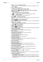
1.
∗
On/off button
Press the button and the system will start. Press the button again and the system will stop.
2.
∗
Operation lamp (red)
The lamp lights up during operation or blinks if a malfunction occurs.
3.
∗
Display “
” (changeover under control)
May be displayed when combined with a VRV-system air conditioner.
It is impossible to changeover heat/cool with the remote controller when this icon is displayed.
4. Display “
” (air flow flap)
This displays the direction and mode of the air flow flap of the combined air conditioner.
Remote controller for VRV BRC1A62
6 2
UNIT No.
GROUP
Remote controller for VKM BRC1D527 (EU only)
1
3
2
4
5
6
9
7
25
13 30
10
31
32
11
38
12
26
41
42
18
17
40
16
29
28
39
36
34
37
35
33
27
20
19
22
5
Summary of Contents for VKM100GAMV1
Page 9: ...Introduction Si71 812 viii ...
Page 43: ...Operation Si71 812 34 Operation ...
Page 53: ...Inspection and Maintenance of the Humidifier Si71 812 44 Maintenance ...
Page 91: ...Troubleshooting Si71 812 82 Troubleshooting ...
Page 99: ...Appendix Si71 812 90 Appendix 1 Appendix 1 1 Wiring Diagram VKM50GAMV1 VKM80GAMV1 VKM100GAMV1 ...
Page 100: ...Si71 812 Appendix Appendix 91 VKM50GAV1 VKM80GAV1 VKM100GAV1 ...
Page 103: ...Piping Diagram Si71 812 94 Appendix ...
Page 105: ...Si71 812 ii Index ...


