Product Specification
Si71-812
10
Product Specification
1.3
Humidifier
Note:
1. Feed clean water (city water, tap water or equivalent) Dirty water may clog the valve or cause dirt
deposits in the water container, resulting in poor humidifier performance. (Never use any cooling tower
water and heating - purpose water.)
Also, if the supply water is hard water, use a water softener because of short life.
∗
Life of humidifying element is about 3 years (4,000 hours), under the supply water conditions of
hardness: 150 mg/l. (Life of humidifying element is about 1 year (1,500 hours) under the supply water
conditions of hardness: 400 mg/l.)
Annual operating hours: 10 hours / day × 26 days / month × 5 month = 1,300 hours
2. Maintain the supply water temperature at 5 ~ 50°C and its pressure at 20 ~ 490 kPa (0.2 ~ 5.0 kg/cm
2
).
If the water pressure is above 490 kPa (5.0 kg/cm
2
), add pressure reducing valve in between the kit
and the supply water shut - off valve.
3. The supply water line cannot be directly connected with a utility water tap. To unavoidably take water
from such line, employ a CISTERN (gotten configuration authorization).
4. Be sure to provide thermal insulation around the indoor piping as well as the shut - off valves.
5. In order to prevent harmful bacteria from generating, do maintenance on humidifying unit portion at the
beginning and the end of the heating season according to the operation manual.
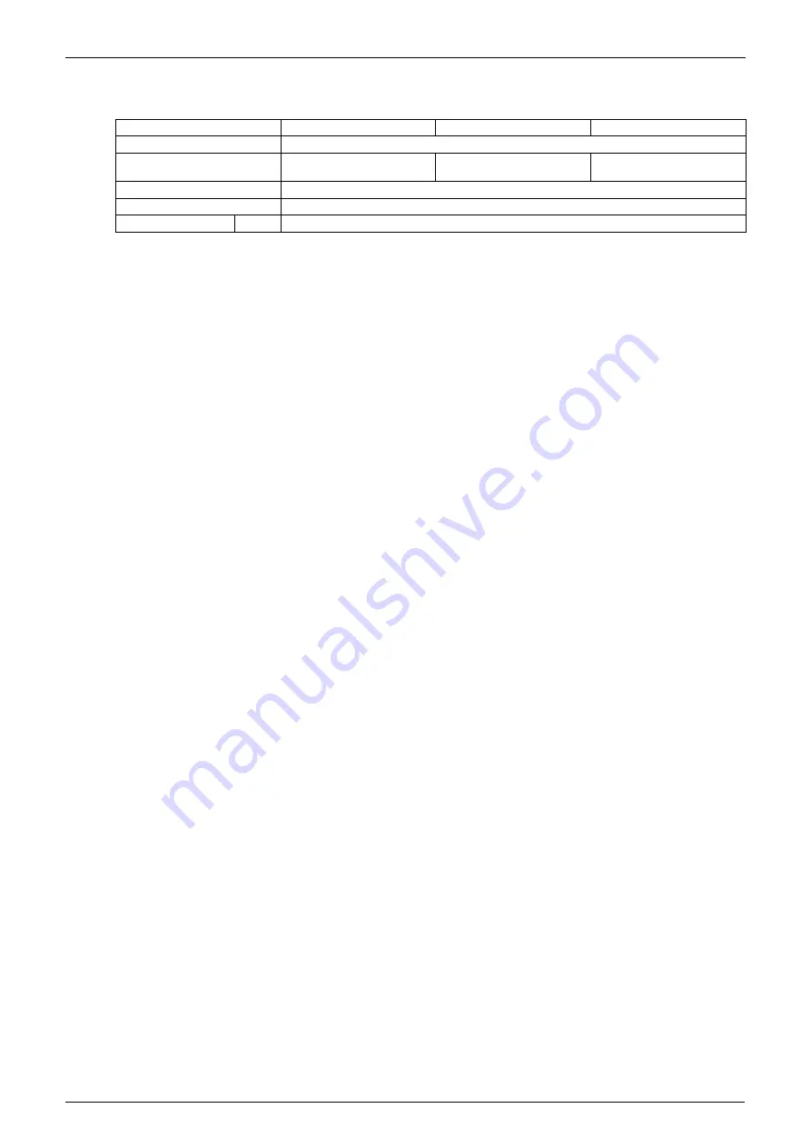
VKM50GAMV1
VKM80GAMV1
VKM100GAMV1
Humidifier type
Natural evaporating type humidifier
Wetted element
Porosity plate 60 pcs.
Porosity plate 90 pcs.
Porosity plate 120 pcs.
(60×2 pcs.)
Water inlet port
φ
6.4 C1220T (Flare Connection)
Water outlet port
PT3/4
Supply water pressure kg/cm
2
0.2 (Min.) ~ 5.0 (Max.)
Summary of Contents for VKM100GAMV1
Page 9: ...Introduction Si71 812 viii ...
Page 43: ...Operation Si71 812 34 Operation ...
Page 53: ...Inspection and Maintenance of the Humidifier Si71 812 44 Maintenance ...
Page 91: ...Troubleshooting Si71 812 82 Troubleshooting ...
Page 99: ...Appendix Si71 812 90 Appendix 1 Appendix 1 1 Wiring Diagram VKM50GAMV1 VKM80GAMV1 VKM100GAMV1 ...
Page 100: ...Si71 812 Appendix Appendix 91 VKM50GAV1 VKM80GAV1 VKM100GAV1 ...
Page 103: ...Piping Diagram Si71 812 94 Appendix ...
Page 105: ...Si71 812 ii Index ...


