Inspection and Maintenance of the Humidifier
Si71-812
40
Maintenance
2.1.2
Inspection of the Feed Water Tank
Check for Dirt
1. Remove the maintenance cover.
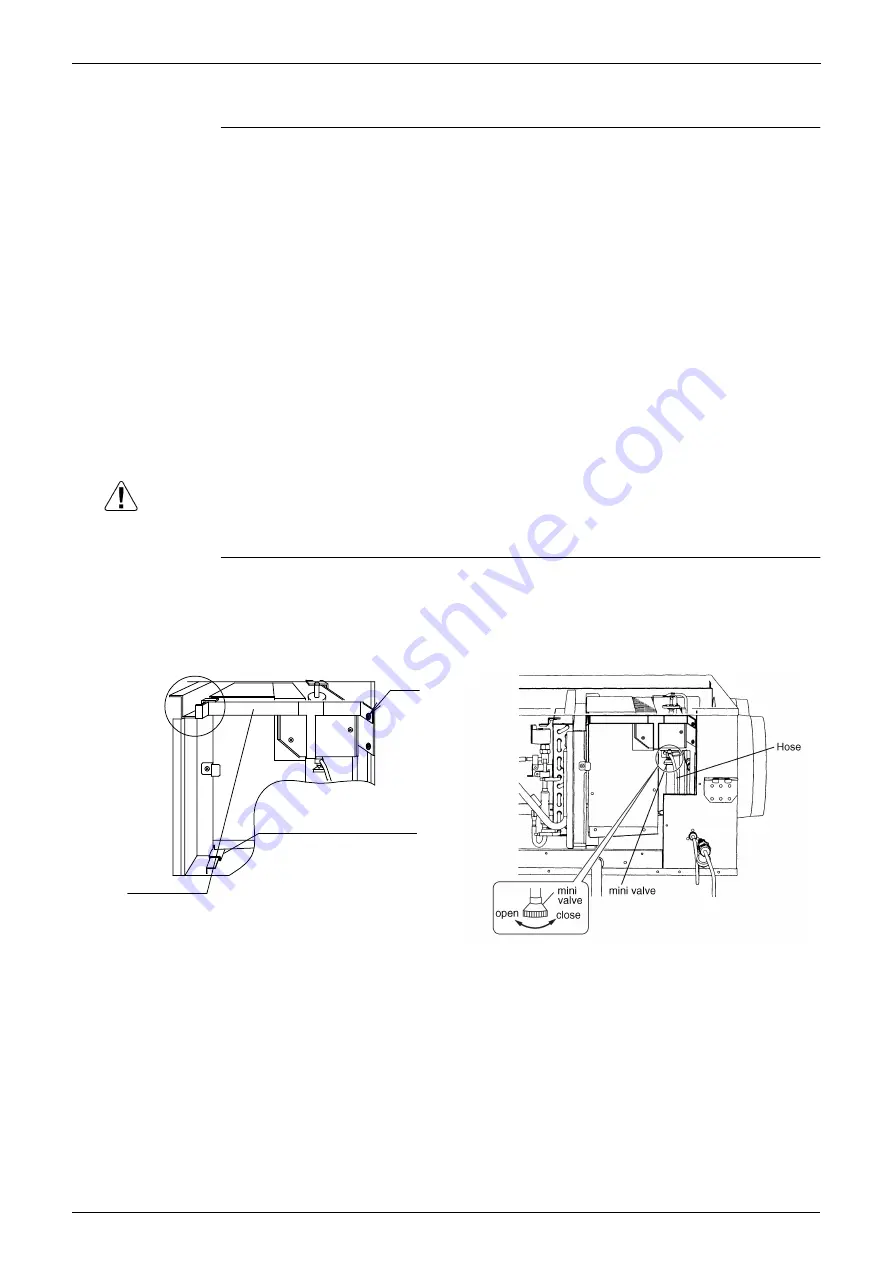
2. Before cleaning or replacing, remove the supporting stay. (Fig.3)
3. Please loosen a mini valve and drain the water which has accumulated. (Fig.4)
4. Remove the cover of the feed water tank. (Fig.5)
5. Remove the hold plate. (Fig.5)
6. Pull out the Humidifier elements. (Fig.5)
7. Check inside the feed water tank
8. Please use the point of the long stick more than 85cm.
Please wipe off the contamination inside a feed water tank. (Fig.6)
(The length to the depths of a water tank VKM50GAMV1: 40cm, VKM80,100GAMV1 73cm)
9. Push in the Humidifier elements. (Fig.4)
10.Install the hold plate. (Fig.4)
11.Install the cover of the feed water tank. (Fig.4)
12.• Confirm that the link of the supporting stay has been hooked securely on the rail and insert
it. (Fig.8)
• Refit the supporting stay handling part without contacting the lid of feed water tank. (Fig.8)
• Insert the supporting stay securely and fix it with the screws. (Fig.8)
13.Install the maintenance cover.
Caution
Clean inside the feed water tank taking care not to pierce the float switch.
It will break when strongly pushed.
Check for
Operation of
Float Switch
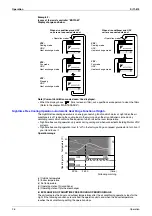
<Please check whether there is any defect of operation by scale.>
When you raised and detach a float switch by hand, please check that a float switch falls. (Fig.7)
Fig. 3
Fig. 4
screw
supporting stay
spacer for the humidifier element
Confirm that the humidifier
element has been on the spacer
and insert it.
Summary of Contents for VKM100GAMV1
Page 9: ...Introduction Si71 812 viii ...
Page 43: ...Operation Si71 812 34 Operation ...
Page 53: ...Inspection and Maintenance of the Humidifier Si71 812 44 Maintenance ...
Page 91: ...Troubleshooting Si71 812 82 Troubleshooting ...
Page 99: ...Appendix Si71 812 90 Appendix 1 Appendix 1 1 Wiring Diagram VKM50GAMV1 VKM80GAMV1 VKM100GAMV1 ...
Page 100: ...Si71 812 Appendix Appendix 91 VKM50GAV1 VKM80GAV1 VKM100GAV1 ...
Page 103: ...Piping Diagram Si71 812 94 Appendix ...
Page 105: ...Si71 812 ii Index ...


