14 Unit installation
Installation and operation manual
26
REMA5+REYA8~20A7Y1B
VRV 5 heat recovery
4P684060-1 – 2022.02
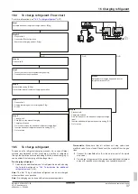
Flow chart (for EACH BS unit branch pipe port)
Procedure to check if
smallest room size meets
requirements
Continued on next column/page
Derive maximum indoor capacity
to connect to branch pipe port.
See step 2 in above text.
Determine smallest room area
served by same branch pipe port.
See step 1 in above text.
Change installation for this port:
1. Increase area of smallest room.
OR
2. Reduce connected indoor capacity
below limit
OR
3. Add additional countermeasures
as described in applicable legislation.
OR
4. Split indoor capacity over 2 separate
BS unit ports.
OR
5. Fine tune system with
VRV Xpress
.
Total indoor capacity index
<
Capacity index limit?
A
min
[m²]
Indoor capacity
class limit
YES
YES
NO
Any indoor units on
lowest underground floor?
NO
Start installation
Procedure to check if
smallest area of lowest
underground floor meets the
requirements
Start installation
Derive maximum system charge.
See step 3 in above text.
Determine smallest room area
of the lowest underground floor.
Change installation for this port:
1. Increase area of smallest underground
room.
OR
2. Decrease piping length by changing layout
OR
3. Add additional countermeasures
as described in applicable legislation.
Total charge amount
<
Total charge limit?
A
min
[m²]
Total charge limit
[kg]
Derive total charge amount.
See step 4 in above text.
Total charge amount
[kg]
YES
NO
Continued from previous column/page
14
Unit installation
WARNING
The installation MUST comply with the requirements that
apply to this R32 equipment. For more information, see
"13 Special requirements for R32 units"
14.1
Preparing the installation site
WARNING
The appliance shall be stored in a room without
continuously operating ignition sources (example: open
flames, an operating gas appliance or an operating electric
heater).


