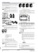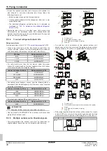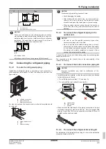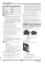
15 Piping installation
Installation and operation manual
30
REMA5+REYA8~20A7Y1B
VRV 5 heat recovery
4P684060-1 – 2022.02
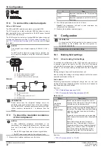
▪ In case the required pipe sizes (inch sizes) are not available, it is
also allowed to use other diameters (mm sizes), taken the
following into account:
▪ Select the pipe size nearest to the required size.
▪ Use the suitable adapters for the change-over from inch to mm
pipes (field supply).
▪ The additional refrigerant calculation has to be adjusted as
mentioned in
"16.3 To determine the additional refrigerant
36].
▪ Applicable pipe size up is decided upon field piping rules
determined by the installation needs. See technical data and
installer user reference guide for more details about the required
pipe size up for your installation.
15.1.4
To select refrigerant branch kits
Refrigerant refnets
"15.1.3 To select the piping size"
29].
▪ When using refnet joints at the first branch counted from the
outdoor unit side, choose from the following table in accordance
with the capacity of the outdoor unit (example: refnet joint c).
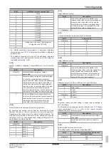
HP class
Refrigerant branch kit
8+10
KHRQ23M29T9
12~20
KHRQ23M64T
22~28
KHRQ23M75T
▪ For refnet joints other than the first branch, select the proper
branch kit model based on the total capacity index of all indoor
units connected after the refrigerant branch.
Indoor unit capacity index
Refrigerant branch kit
<200
KHRQ23M20T
200≤x<290
KHRQ23M29T9
290≤x<640
KHRQ23M64T
≥640
KHRQ23M75T
▪ Concerning refnet headers, choose from the following table in
accordance with the total capacity of all the indoor units connected
below the refnet header.
Indoor unit capacity index
Refrigerant branch kit
<290
KHRQ23M29H
290≤x<640
KHRQ23M64H
≥640
KHRQ23M75H
▪ For refnet joints between BS unit and indoor units
Indoor unit capacity index
Refrigerant branch kit
≤250
KHRQ22M20TA
INFORMATION
Maximum 8 branches can be connected to a header.
▪ Use the branch kit BHFQ23P907 for a outdoor multi connection
piping kit for 2 outdoor units.
15.1.5
Multiple outdoor units: Possible layouts
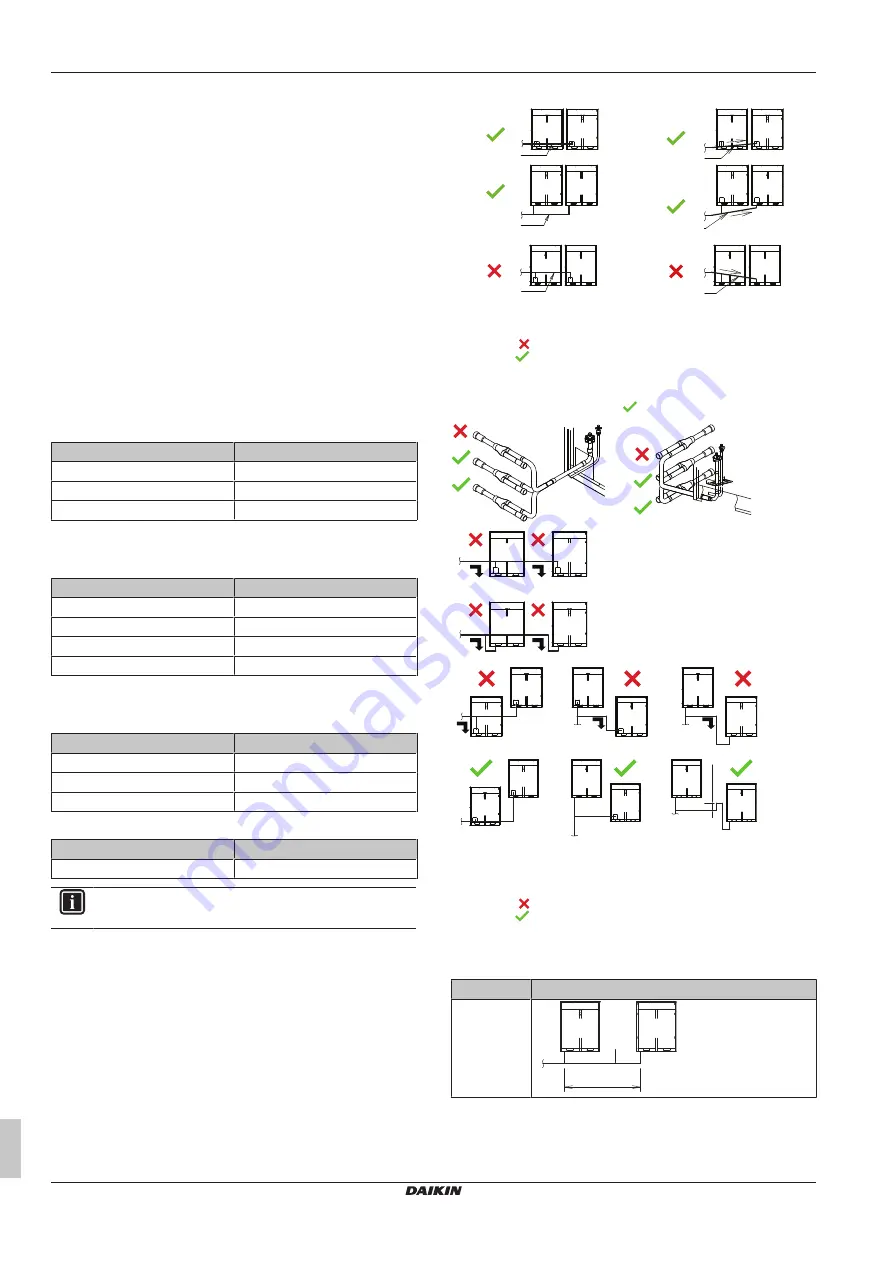
▪ The piping between the outdoor units must be routed level or
slightly upward to avoid the risk of oil retention into the piping.
Pattern 1
a
b
b
a
Pattern 2
b
a
a
b
a
b
b
a
a
To indoor unit
b
Piping between outdoor units
NOT allowed (oil remains in piping)
Allowed
▪ To avoid the risk of oil retention to the outmost outdoor unit,
always connect the stop valve and the piping between outdoor
units as shown in the correct (
) possibilities of the figure below.
a
b
b
a
b
b
a
b
a
b
a
b
a
a
a
≥200 mm
a
To indoor unit
b
Oil collects to the outmost outdoor unit when the system
stops
NOT allowed (oil remains in piping)
Allowed
▪ If the piping length between the outdoor units exceeds 2 m, create
a rise of 200 mm or more in the suction gas line and the high
pressure/low pressure gas line within a length of 2 m from the kit.
If
Then
≤2 m
a
b
≤2 m


