17 Electrical installation
Installation and operation manual
40
REMA5+REYA8~20A7Y1B
VRV 5 heat recovery
4P684060-1 – 2022.02
For standard combinations
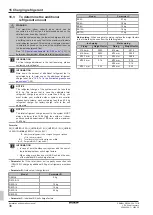
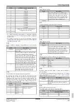
Selection and sizing of the wiring should be done in accordance with
the applicable legislation based on the information mentioned in the
table below.
Single outdoor unit
Model
Minimum circuit
ampacity
Recommended fuses
REMA5
15.0 A
20 A
REYA8
16.1 A
20 A
REYA10
22.0 A
25 A
REYA12
24.0 A
32 A
REYA14
27.0 A
32 A
REYA16
31.0 A
40 A
REYA18
35.0 A
40 A
REYA20
42.0 A
50 A
For all models:
▪ Phase and frequency: 3N~ 50 Hz
▪ Voltage: 380~415 V
For non-standard combinations
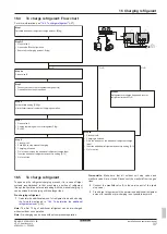
Calculate the recommended fuse capacity.
Formula
Calculate, by adding the minimum circuit amps of each
used unit (according to the table above), multiply the
result by 1.1 and select the next higher recommended
fuse capacity.
Example
Combining the REYA24 by using the REYA10 and
REYA14.
▪ Minimum circuit ampacity of the REYA10=22.0 A
▪ Minimum circuit ampacity of the REYA14=27.0 A
Accordingly, the minimum circuit ampacity of the
REYA24=22.0+27.0=49.0 A
Multiply the above result by 1.1: (49.0 A×1.1)=53.9 A,
so the recommended fuse capacity would be
63 A
.
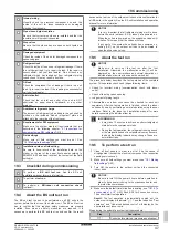
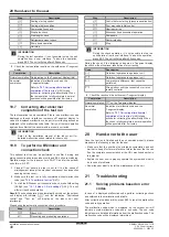
NOTICE
When using residual current operated circuit breakers, be
sure to use a high-speed type 300 mA rated residual
operating current.
17.3
To route and fix the transmission
wiring
NOTICE
Sheathed
and
shielded
cables
are
required
for
transmission wiring between outdoor unit and BS unit.
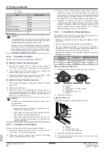
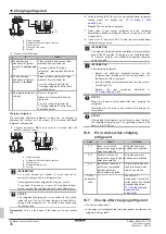
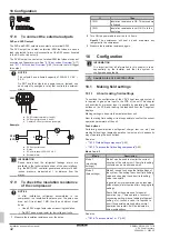
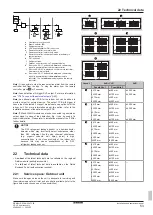
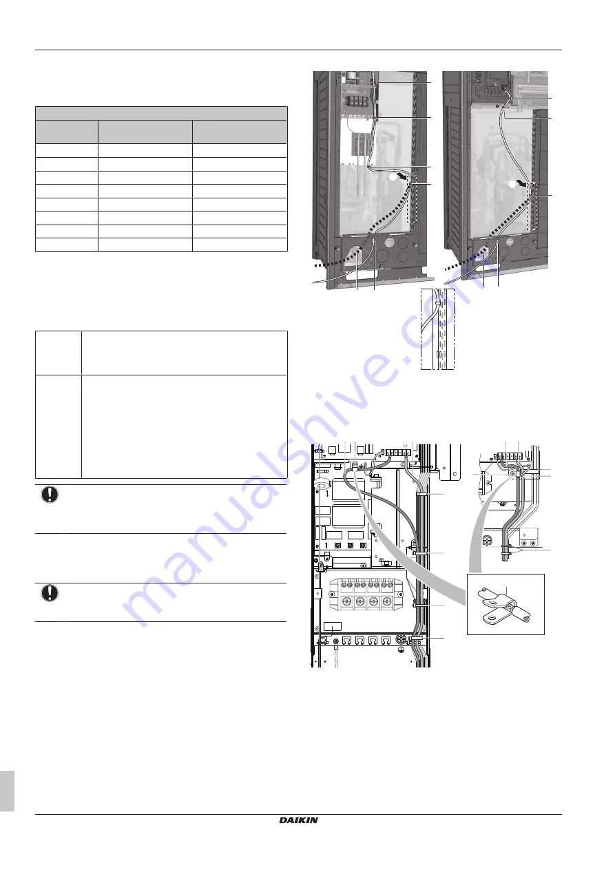
Transmission wiring can be routed through the front side only. Fix it
to the upper mounting hole.
b
a
A
b a
c
c
c
d
c
d
c
5~12 HP
14~20 HP
A
A
a
Transmission wiring (possibility 1)
(a)
b
Transmission wiring (possibility 2)
(a)
c
Tie wrap. Fix to factory-mounted low voltage wiring.
(a)
Knockout hole has to be removed. Close the hole to
avoid small animals or dirt from entering.
X1A
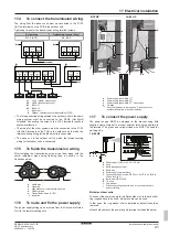
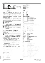
b
5~12 HP
14~20 HP
e
a e
c
d
d
d
d
d
d
a b
e
a
Wiring between the units (indoor-outdoor) (F1/F2 left)
b
Internal transmission wiring (Q1/Q2)
c
Plastic bracket
d
Tie wrap (field supply)
e
P-clamp for cable shield earthing
Fix to the indicated plastic brackets using field supplied clamping
material.
The wiring for F1/F2 indoor transmission must be shielded wire. The
shielding is earthed via a metal P-clamp (e). Strip the insulation up to
the shielding mesh, to provide full contact of the earth with the
shielding.


