22 Technical data
Installation and operation manual
53
REMA5+REYA8~20A7Y1B
VRV 5 heat recovery
4P684060-1 – 2022.02
c
i
a
d
e
f
d
c
c
d
d
g
k
l
m
l
j
h
b
a
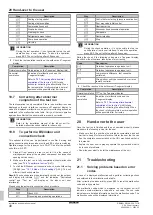
Heat recovery outdoor unit
b
Branch selector (BS)
c
Refrigerant piping
d
VRV direct expansion (DX) indoor unit
e
Remote controller in normal mode
f
Remote controller in alarm only mode
g
Remote controller in supervisor mode (mandatory in
some situations)
h
iTM (optional)
i
Refrigerant leak
j
Outdoor unit error code on 7‑segment display
k
Error code 'A0–11' and audible alarm and red warning
signal is generated from this remote controller.
l
Error code 'U9–02' is displayed on this remote controller.
No alarm or warning lights.
m
Error code 'A0–11' and audible alarm and red warning
signal is generated from this
supervisor
remote
controller. The unit
address
is displayed on this remote
controller.
Note:
It is possible to stop the leak detection alarm from the remote
controller and from the app. To stop the alarm from the remote
controller, press
for 3 seconds.
Note:
Leak detection will trigger SVS output. For more information,
"17.8 To connect the external outputs"
Note:
An optional output PCB for the indoor unit can be added to
provide output for external device. The output PCB will trigger in
case a leak is detected. For exact model name see option list of the
indoor unit. For more information about this option, refer to the
installation manual of the optional output PCB
Note:
iTM and WAGO module can also be connected to generate an
output signal in case of leak detection. E.g. it can be used at a
supervised location. Please refer to installation manual of the iTM for
further details.
NOTICE
The R32 refrigerant leakage sensor is a semiconductor
detector which may incorrectly detect substances other
than R32 refrigerant. Avoid using chemical substances
(e.g. organic solvents, hair spray, paint) in high
concentrations, in the close proximity of the indoor unit
because this may cause misdetection of the R32
refrigerant leakage sensor.
22
Technical data
▪ A
subset
of the latest technical data is available on the regional
Daikin website (publicly accessible).
▪ The
full set
of latest technical data is available on the Daikin
Business Portal (authentication required).
22.1
Service space: Outdoor unit
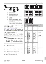
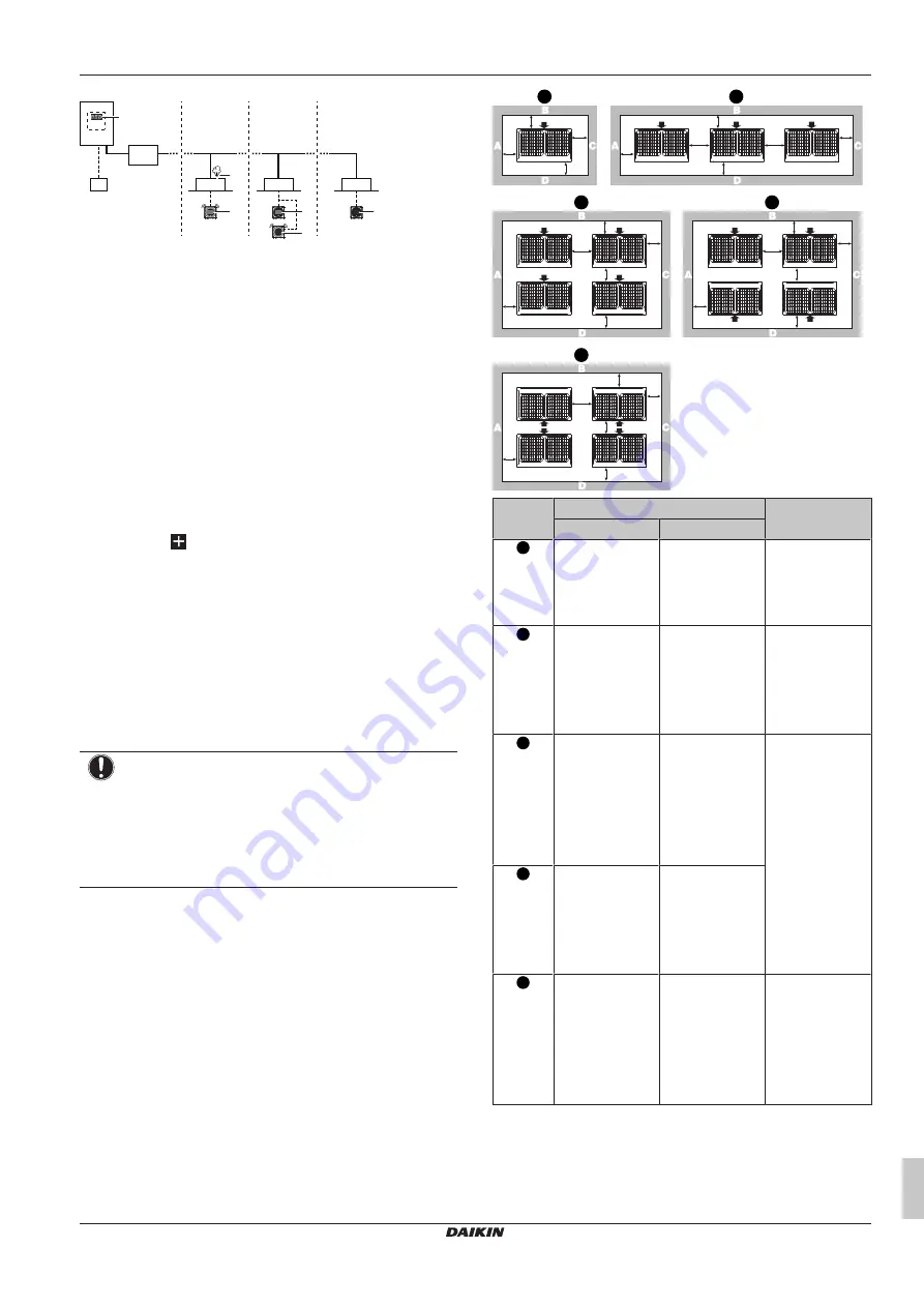
Make sure the space around the unit is adequate for servicing and
the minimum space for air inlet and air outlet is available (refer to the
figure below and choose one of the possibilities).
a
b
a
c
d
a
b
a
e
d
e
c
a
b
a
e
d
f
c
a
b
a
e
b
d
c
a
b
a
e
d
f
c
1
2
3
4
5
Layout
A+B+C+D
A+B
Possibility 1
Possibility 2
1
a≥10 mm
b≥300 mm
c≥10 mm
d≥500 mm
a≥50 mm
b≥100 mm
c≥50 mm
d≥500 mm
a≥200 mm
b≥300 mm
2
a≥10 mm
b≥300 mm
c≥10 mm
d≥500 mm
e≥20 mm
a≥50 mm
b≥100 mm
c≥50 mm
d≥500 mm
e≥100 mm
a≥200 mm
b≥300 mm
e≥400 mm
3
a≥10 mm
b≥300 mm
c≥10 mm
d≥500 mm
e≥20 mm
f≥600 mm
a≥50 mm
b≥100 mm
c≥50 mm
d≥500 mm
e≥100 mm
f≥500 mm
—
4
a≥10 mm
b≥300 mm
c≥10 mm
d≥500 mm
e≥20 mm
a≥50 mm
b≥100 mm
c≥50 mm
d≥500 mm
e≥100 mm
5
a≥10 mm
b≥500 mm
c≥10 mm
d≥500 mm
e≥20 mm
f≥900 mm
a≥50 mm
b≥500 mm
c≥50 mm
d≥500 mm
e≥100 mm
f≥600 mm
—


