15 Piping installation
Installation and operation manual
29
REMA5+REYA8~20A7Y1B
VRV 5 heat recovery
4P684060-1 – 2022.02
15.1
Preparing refrigerant piping
15.1.1
Refrigerant piping requirements
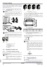
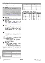
NOTICE
The piping and other pressure-containing parts shall be
suitable for refrigerant. Use phosphoric acid deoxidised
seamless copper for refrigerant.
▪ Foreign materials inside pipes (including oils for fabrication) must
be ≤30 mg/10 m.
15.1.2
Refrigerant piping material
▪
Piping material:
Phosphoric acid deoxidised seamless copper.
▪
Flare connections:
Only use annealed material.
▪
Piping temper grade and thickness:
Outer diameter
(Ø)
Temper grade
Thickness (t)
(a)
6.4 mm (1/4")
9.5 mm (3/8")
12.7 mm (1/2")
Annealed (O)
≥0.80 mm
t
Ø
15.9 mm (5/8")
Annealed (O)
≥0.99 mm
19.1 mm (3/4")
22.2 mm (7/8")
Half hard (1/2H)
≥0.80 mm
28.6 mm (1 1/8")
Half hard (1/2H)
≥0.99 mm
(a)
Depending on the applicable legislation and the maximum
working pressure of the unit (see "PS High" on the unit name
plate), larger piping thickness might be required.
15.1.3
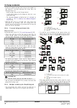
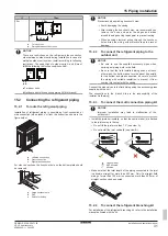
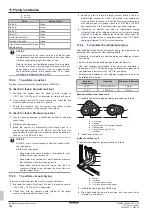
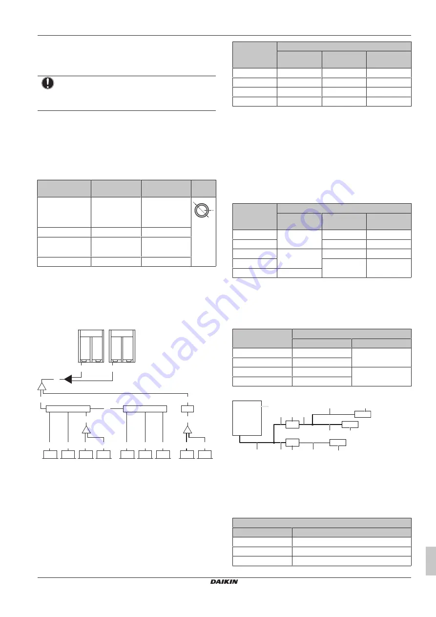
To select the piping size
Determine the proper size using the following tables and reference
figure (only for indication).
B
A
B
c
e
C
C
D
D
d
b
3
a
8
a
9
D
D
d
a
3
a
4
a
1
a
2
C'
D
D
C''
C
b
1
a
5
a
6
D
a
7
D
D
b
2
a1~a9
VRV DX indoor units
b1~b3
Branch selector units (BS)
c
First indoor branch kit (refnet)
d
Indoor branch kit (refnet)
e
Outdoor multi connection kit
A~D
Piping
A, B: Piping between outdoor unit and (first)
refrigerant branch kit
Choose from the following table in accordance with the outdoor unit
total capacity type. Pipe A is in case of multi-connection the sum of
the outdoor units connected upstream.
HP class
Piping outer diameter [mm]
Liquid pipe
Suction gas
pipe
HP/LP gas
pipe
5~10
9.5
19.1
15.9
12~18
12.7
22.2
19.1
20~24
12.7
28.6
22.2
26~28
15.9
28.6
22.2
C: Piping between refrigerant branch kits, BS
units, or refrigerant branch kits and BS units
Choose from the following table in accordance with the indoor unit
total capacity type, connected downstream. Do not let the
connection piping exceed the refrigerant piping size chosen by the
general system model name.
Example:
▪ Downstream
capacity
for
C'=[capacity
index
of
unit a1]+[unit a2]+[unit a3]+[unit a4]+[unit a5]+[unit a6]+[unit a7]
▪ Downstream capacity for C''=[capacity index of unit a3]+[unit a4]
Indoor unit
capacity index
Piping outer diameter [mm]
Liquid pipe
Suction gas
pipe
HP/LP gas
pipe
<150
9.5
15.9
12.7
150≤x<290
19.1
15.9
290≤x<450
12.7
22.2
19.1
450≤x<620
28.6
22.2
≥620
15.9
D: Piping between refrigerant branch kit or BS unit
and indoor unit
Pipe size for direct connection to indoor unit must be the same as
the connection size of the indoor unit (in case indoor unit is VRV DX
indoor).
Indoor unit capacity
index
Piping outer diameter [mm]
Gas pipe
Liquid pipe
10~32
9.5
6.4
40~80
12.7
100~140
15.9
9.5
200~250
19.1
▪ If a size-up of the piping is required, refer to the table below.
e
e
e
h
g
g
g
h
h
b
d
c
a
f
f
a
Outdoor unit
b
Main pipes (increase size)
c
First refrigerant branch kit
d
Last refrigerant branch kit
e
Indoor unit
f
BS unit
g
Piping between first and last refrigerant branch kit
(increase size)
h
Piping between last refrigerant branch kit and indoor unit
Size up
HP class
Liquid piping outer diameter [mm]
5~10
9.5
→
12.7
12~24
12.7
→
15.9
26~28
15.9
→
19.1


