22 Technical data
Installation and operation manual
54
REMA5+REYA8~20A7Y1B
VRV 5 heat recovery
4P684060-1 – 2022.02
h
1
h
2
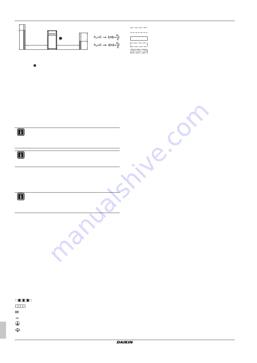
1500
500
F
(mm)
d
b
ABCD
Sides along the installation site with obstacles
F
Front side
Suction side
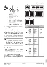
▪ In case of an installation site where sides A+B+C+D have
obstacles, the wall heights of sides A+C have no impact on
service space dimensions. Refer to the figure above for impact of
wall heights of sides B+D on service space dimensions.
▪ In case of an installation site where only the sides A+B have
obstacles, the wall heights have no influence on any indicated
service space dimensions.
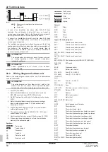
▪ The installation space required on these drawings are for full load
heating operation without considering possible ice accumulation. If
the location of the installation is in a cold climate, then all
dimensions above should be >500 mm to avoid accumulation of
ice in between the outdoor units.
INFORMATION
The service space dimensions in above figure are based
on cooling operation at 35°C ambient temperature
(standard conditions).
INFORMATION
Further specifications can be found in the technical
engineering data.
22.2
Wiring diagram: Outdoor unit
Refer to the wiring diagram sticker on the unit. The abbreviations
used are listed below:
INFORMATION
The wiring diagram on the outdoor unit is only for the
outdoor unit. For the indoor unit or optional electrical
components, refer to the wiring diagram of the indoor unit.
1
Symbols (see below).
2
Refer to the installation or service manual on how to use
BS1~BS3 push buttons and DS1~DS2 switches.
3
Do NOT operate the unit by short-circuiting protection device
S1PH.
4
Refer to the installation manual for connection wiring to
indoor–outdoor transmission F1‑F2 and outdoor‑multi
transmission Q1‑Q2.
5
When using the central control system, connect outdoor–
outdoor transmission F1‑F2.
6
The capacity of the contact is 220~240V AC – 0.5 A (rush
current needs 3 A or less).
7
Use dry contact for micro current (10 mA or less, 15 V DC).
8
When using the optional adapter, refer to the installation
manual of the optional adapter.
Symbols:
Field wiring
Terminal block
Connector
Terminal
Protective earth
Noiseless earth
Earth wiring
Field supply
PCB
Switch box
Option
Colours:
BLK
Black
RED
Red
BLU
Blue
WHT
White
GRN
Green
Legend for wiring diagram
A1P
Printed circuit board (main)
A2P
Printed circuit board (noise filter)
A3P
Printed circuit board (inverter)
A4P
Printed circuit board (fan)
A5P (14~20 HP
only)
Printed circuit board (fan)
A6P (14~20 HP
only)
Printed circuit board (sub)
BS1~BS3 (A1P) Push button switch (MODE, SET, RETURN)
DS1, DS2
(A1P)
DIP switch
E1HC
Crankcase heater
E3H
Bottom plate heater
F1U (A1P)
Fuse (T 10 A / 250 V)
F1U (A6P)
(14~20 HP
only)
Fuse (T 3.15 A / 250 V)
F1U, F2U
Fuse (T 1 A / 250 V)
F3U
Field fuse
F101U (A4P)
Fuse
HAP (A*P)
Pilot lamp (service monitor is green)
K*R (A*P)
Relay on PCB
L1R
Reactor
M1C
Motor (compressor)
M1F
Motor (fan)
M2F (14~20 HP
only)
Motor (fan)
Q1DI
Earth leakage circuit breaker
R1T
Thermistor (air)
R3T
Thermistor (liquid, main)
R4T
Thermistor (heat exchanger, liquid pipe upper)
R5T
Thermistor (heat exchanger, liquid pipe lower)
R6T
Thermistor (subcool heat exchanger gas)
R7T
Thermistor (subcool heat exchanger liquid)
R8T
Thermistor (heat exchanger, gas upper)
R9T
Thermistor (heat exchanger, gas lower)
R10T
Thermistor (suction)
R11T
Thermistor (heat exchanger, de-icer)
R12T
Thermistor (suction compressor)
R13T
Thermistor (receiver gas)
R15T
Thermistor (M1C body)
R16T (5~12 HP
only)
Thermistor (gas injection)


