17 Commissioning
Installation and operation manual
42
SV1ASV4~8A14AJV1B
VRV 5 safety valve unit
4P709466-1 – 2023.09
▪
No safety measure:
all SV units with no safety measures.
▪
External alarm:
all SV units with an external alarm.
▪
Natural ventilation:
all SV units with natural ventilation
▪
Ventilated enclosure
–
one SV
unit to one extraction fan
configuration:
all SV units with a ventilated enclosure – one-to-
one configuration.
▪
Ventilated enclosure
–
multiple SV
units to one extraction fan,
parallel configuration:
all SV units with a ventilated enclosure –
parallel configuration.
▪
Ventilated enclosure
–
multiple SV
units to one extraction fan,
series configuration:
only one SV unit with a ventilated
enclosure – series configuration. Tip: choose the SV unit which is
most upstream, where the air inlet (damper) is free and you can
measure the airflow rate.
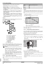
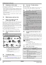
Example
In the example below: change the setting [2-3] to start the test run
for the following SV units: a, b, d, e, f, g and h.
l
k
k
a
b
c
d
e
g
f
j
h
k
i
a
SV unit in one-to-one configuration
b
SV unit in series configuration
c
SV unit in series configuration
d
SV unit in parallel configuration
e
SV unit in parallel configuration
f
SV unit without safety measures
g
SV unit with external alarm
h
SV unit with natural ventilation
i
Natural ventilation
j
External alarm
k
Extraction fan
l
Outdoor unit
Interconnection wiring
In case the safety measures demand a ventilated enclosure, the SV
unit test run has to include a measurement of the actual extraction
airflow rate to confirm that it meets the legal requirements.
NOTICE
It is very important that all refrigerant piping work is done
before the units (outdoor, SV or indoor) are powered.
When the units are powered, the expansion valves
initialise. This means that the valves close.
If any part of the system had already been powered before,
FIRST activate setting [2-21] on the outdoor unit to open
the expansion valves again THEN power off the unit to
conduct the SV unit test run.
17.2.2
About airflow requirements
When a ventilated enclosure is required, the following requirements
apply:
▪ pressure inside the SV unit has to be more than 20 Pa below the
ambient pressure,
▪ minimum airflow rate:
Model
Minimum airflow rate [m³/h]
SV1A
82
SV4A
82
SV6~8A
84
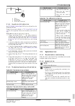
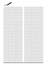
Example
A SV8A unit with an airflow rate during the test run of 115 m³/h. The
pressure drop graph shows that this results in an internal pressure
which is 38 Pa below the ambient pressure. Both requirements are
met:
▪ The pressure inside the SV unit is more than 20 Pa below the
ambient pressure (38 Pa).
▪ The airflow rate is higher than 84 m³/h (115 m³/h).
- 38.01
115
P
INTERNAL
[Pa]
-300
-250
-200
-150
-100
0
0
50
100
150
200
250
300
-50
AFR
OUT
[m³/h]
AFR
OUT
Airflow rate [m³/h]
P
internal
Internal pressure below ambient pressure [Pa]
See the latest version of the technical engineering data for the SV
unit's pressure drop curves.
17.2.3
About measuring the airflow rate
It is up to the installer to measure the airflow rate and provide correct
data. We advise two ways in the sections below, but the installer is
entirely free on how to perform the measurement.
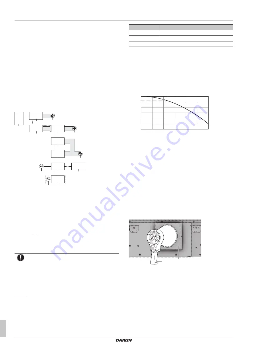
About measuring with a vane anemometer
▪ Where: Measure the airflow rate at the air inlet (damper) of the SV
unit.
▪ Tip: Use the duct connection kit (EKBSDCK) and an anemometer
with a funnel to conduct the entire airflow through the
anemometer.
▪ Postrequisite: Remove the kit once the measurement is finished.
b
a
a
Vane anemometer
b
Duct connection kit (EKBSDCK)
About measuring with a hot wire probe anemometer
▪ Attention: In case you need to drill holes in the ducting, choose a
location without thermal insulation.
▪ Where: Measure the airflow rate in the duct connected to the air
outlet of the SV unit.
▪ Postrequisite: Close the holes properly once the measurement is
finished.
Summary of Contents for VRV 5
Page 47: ......


