17 Commissioning
Installation and operation manual
43
SV1ASV4~8A14AJV1B
VRV 5 safety valve unit
4P709466-1 – 2023.09
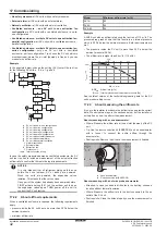
a
d
b
c
a
SV unit
b
Air outlet duct
c
Direction airflow
d
Hot wire probe anemometer
17.2.4
To perform a SV unit test run
See
"16.1.8 Mode 2: field settings"
39] for more information on the
settings that are used.
Respect the sequence indicated in
"17.2.1 About the SV unit test
41]. Do not perform a test run on more than one SV unit at a
time.
Prerequisite:
All refrigerant piping work is finished.
1
Change field setting [2‑3] to "1". This setting simulates a
refrigerant leak and activates the safety measures according to
the field settings that have been made. See
41] to check which units need a setting
change.
2
In case of a configuration with an external alarm, check that the
external alarm warns both audibly (15 dBA above the sound of
the surroundings) and visibly.
3
In case of a configuration with a ventilated enclosure, measure
the airflow rate. See
"17.2.3 About measuring the airflow
42] for more information.
4
In all configurations, check if no safety measures are activated
that are not intended to activate.
5
Change field setting [2‑3] to "0". This setting deactivates the test
run.
6
Change field setting [2‑6] to "1" for all SV units of the system,
even those where the test run was not activated (e.g.
downstream SV units in a ventilated enclosure series
configuration). This setting confirms that the safety measures
are working correctly and - in the case of ventilated enclosure –
it confirms that the extraction airflow rate complies to the legal
limits.
17.2.5
Troubleshooting during a SV unit test run
Symptom: The damper does not open
Possible causes
Corrective action
Incorrect field settings
Check if all field settings are
made correctly. When in parallel
or series configuration, the field
settings of all SV units in a
cluster need to be made
correctly.
Damper wiring is loose
Reattach any loose damper
wiring.
Damper blocked
Remove blocking objects.
Symptom: The extraction fan does not turn ON
Possible causes
Corrective action
Incorrect field settings
Check if all field settings are
made correctly. When in parallel
or series configuration, the field
settings of all SV units in a
cluster need to be made
correctly.
Possible causes
Corrective action
Fan extraction circuit broken
▪ Check that the circuit exists.
▪ Check that the circuit is
connected correctly.
▪ Check that the circuit is
powered.
Symptom: The airflow rate is too low
Possible causes
Corrective action
Incorrect field settings
Check if all field settings are
made correctly. When in parallel
or series configuration, the field
settings of all SV units in a
cluster need to be made
correctly.
▪ When in parallel configuration:
check that no dampers of
other SV units in the same
cluster have opened.
▪ When in series configuration:
check that all dampers of other
SV units in the same cluster
have opened.
Flow blocked
Remove blocking objects.
Incorrect fan size
Check if the sizing of the fan is
appropriate. Adapt if necessary.
Incorrect fan speed
Check if the fan has different
speed settings. Select a higher
speed if necessary.
17.3
System test run
17.3.1
Checklist before commissioning
Follow the outdoor unit's checklist. See the installation and operation
manual delivered with the outdoor unit.
17.3.2
System test run
NOTICE
Do NOT interrupt the test run.
INFORMATION
▪ Perform the test run according to the instructions in the
outdoor unit manual.
▪ The test run is only completed if there is no malfunction
code displayed on the user interface or the outdoor unit
7‑segment display.
▪ See the service manual for the complete list of error
codes and a detailed troubleshooting guideline for each
error.
Summary of Contents for VRV 5
Page 47: ......


