5 Before operation
Installation and operation manual
10
SV1ASV4~8A14AJV1B
VRV 5 safety valve unit
4P709466-1 – 2023.09
4.1
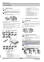
System layout
INFORMATION
The following figure is an example and may NOT
completely match your system layout
a
c
d
e
g
i
f
e
c
c
e
h
i
i
i
b
e
j
a
Heat pump outdoor unit
b
Safety valve unit (SV)
c
VRV direct expansion (DX) indoor unit
d
VRV direct expansion (DX) indoor unit (direct connection
from outdoor to indoor)
e
Remote controller in
normal mode
f
Remote controller in
alarm only mode
g
Remote controller in
supervisor mode
(mandatory in
some situations)
h
Centralised controller (optional)
i
Option PCB (optional)
j
Cool/heat changeover remote control switch (optional)
Refrigerant piping
Interconnection and user interface wiring
Direct connection of indoor units to the outdoor unit
5
Before operation
CAUTION
See
7] to acknowledge all
related safety instructions.
NOTICE
NEVER inspect or service the unit by yourself. Ask a
qualified service person to perform this work.
NOTICE
Turn ON the power 6 hours before operation in order to
have power running to the crankcase heater and to protect
the compressor.
This operation manual is for the following systems with standard
control. Before initiating operation, contact your dealer for the
operation that corresponds to your system type and mark. If your
installation has a customised control system, ask your dealer for the
operation that corresponds to your system.
6
Maintenance and service
6.1
Precautions for maintenance and
service
CAUTION
See
7] to acknowledge all
related safety instructions.
NOTICE
NEVER inspect or service the unit by yourself. Ask a
qualified service person to perform this work.
NOTICE
Maintenance MUST be done by an authorised installer or
service agent.
We recommend performing maintenance at least once a
year. However, applicable legislation might require shorter
maintenance intervals.
Following symbols may occur on the indoor unit:
Symbol
Explanation
Measure the voltage at the terminals of main circuit
capacitors or electrical components before servicing.
6.2
About the refrigerant
CAUTION
See
7] to acknowledge all
related safety instructions.
This product contains fluorinated greenhouse gases. Do NOT vent
gases into the atmosphere.
Refrigerant type: R32
Global warming potential (GWP) value: 675
Periodical inspections for refrigerant leaks may be required
depending on the applicable legislation. Contact your installer for
more information.
NOTICE
Applicable legislation on
fluorinated greenhouse gases
requires that the refrigerant charge of the unit is indicated
both in weight and CO
2
equivalent.
Formula to calculate the quantity in CO
2
equivalent
tonnes:
GWP value of the refrigerant × total refrigerant
charge [in kg]/1000
Contact your installer for more information.
6.2.1
About the refrigerant leakage sensor
WARNING
The R32 refrigerant leakage sensor must be replaced after
every detection or at the end of its lifetime. ONLY
authorised persons may replace the sensor.
NOTICE
The R32 refrigerant leakage sensor is a semiconductor
detector which may incorrectly detect substances other
than R32 refrigerant. Avoid using chemical substances
(e.g. organic solvents, hair spray, paint) in high
concentrations, in the close proximity of the SV unit
because this may cause misdetection by the R32
refrigerant leakage sensor.
NOTICE
Functionality of the safety measures are periodically
automatically checked. In case of malfunction, an error
code will be displayed on the user interface.
INFORMATION
The sensor has a lifetime of 10 years. The user interface
displays error "
CH-22
" 6 months before the end of the
sensor lifetime and error "
CH-23
" after the end of the
sensor lifetime. For more information, see the reference
guide of the user interface and contact your dealer.
Summary of Contents for VRV 5
Page 47: ......


