10 About the box
Installation and operation manual
12
SV1ASV4~8A14AJV1B
VRV 5 safety valve unit
4P709466-1 – 2023.09
For the installer
10
About the box
NOTICE
Before installation, check the packaging and parts for
damage. Make sure that the shipment is complete.
NOTICE
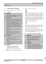
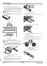
When you carry or manipulate the unit, never tilt it more
than 70 degrees in any direction.
70°max.
Keep the following in mind:
▪ At delivery, the unit MUST be checked for damage and
completeness. Any damage or missing parts MUST be reported
immediately to the claims agent of the carrier.
▪ Bring the packed unit as close as possible to its final installation
position to prevent damage during transport.
▪ Prepare in advance the path along which you want to bring the
unit to its final installation position.
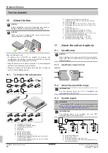
10.1
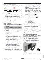
To remove the accessories
n
2/1x
o
1/3/2x
p
1x
q
2x
r
2x
s
1x
t
2x
u
2x
v
2x
f
g
h
b
c
d
1x
1x
1x
1x
1x
1x
e
1x
i
3/1x
j
4/2x
k
2x
l
8/11x
m
1x
a
a
Declaration of conformity
b
Installation and operation manual
c
General safety precautions
d
Drain hose
e
Metal clamp
f
Sealing material (large)
g
Sealing material (small)
h
Sealing material (thin sheet)
i
Insulation tube for stopper pipe Ø9.5 mm (3× for SV4A,
1× for SV1A and SV6~8A)
j
Insulation tube for stopper pipe Ø15.9 mm (4× for SV4A,
2× for SV1A and SV6~8A)
k
Insulation tube for stopper pipe Ø22.2 mm
l
Cable ties (8× for SV4A, 11× for SV1A and SV6~8A)
m
Duct closing plate
n
Stopper pipe Ø9.5 mm (2× for SV4A, 1× for SV6~8A)
o
Stopper pipe Ø15.9 mm (1× for SV1A, 3× for SV4A, 2×
for SV6~8A)
p
Stopper pipe Ø22.2 mm
q
Liquid header reducer pipe (Ø15.9 → 9.5 mm)
r
Liquid header reducer pipe (Ø15.9 → 12.7 mm)
s
Gas branch expander pipe (Ø15.9 → 19.1 mm) (1× for
SV1A for connection to FXMA200/250)
t
Gas header reducer pipe (Ø22.2 → 15.9 mm)
u
Gas header reducer pipe (Ø22.2 → 19.1 mm)
v
Gas header expander pipe (Ø22.2 → 28.6 mm)
11
About the unit and options
11.1
Identification
NOTICE
When installing or servicing several units at the same time,
make sure NOT to switch the service panels between
different models.
11.1.1
Identification label: SV unit
Location
11.2
About the operation range
INFORMATION
For the operation limits, see
11.3
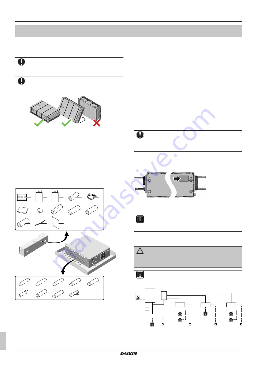
System layout
WARNING
The installation MUST comply with the requirements that
apply to this R32 equipment. For more information, see
"12 Special requirements for R32 units"
INFORMATION
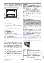
The following figure is an example and may NOT
completely match your system layout
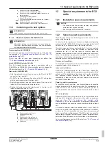
a
c
d
e
g
i
f
e
c
c
e
h
i
i
i
b
e
j
a
Heat pump outdoor unit
b
Safety valve unit (SV)
c
VRV direct expansion (DX) indoor unit
d
VRV direct expansion (DX) indoor unit (direct connection
from outdoor to indoor)
Summary of Contents for VRV 5
Page 47: ......


