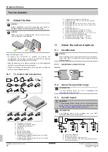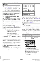
12 Special requirements for R32 units
Installation and operation manual
16
SV1ASV4~8A14AJV1B
VRV 5 safety valve unit
4P709466-1 – 2023.09
12.4
Safety measures
12.4.1
No safety measure
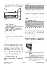
When the room area is sufficiently large, no safety measures are
required. This also includes a SV unit installed in the lowest
underground floor.
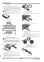
The duct connection must be replaced with the duct closing plate
accessory (see
"13.5.2 To install the duct closing plate"
Field settings
No safety measure
Code
Description
Value
[2-0]
(a)
Cluster indication
0 (default): disable
[2-4]
(b)
Safety measures
0: disable
(a)
Set on ALL main PCBs (A1P and A2P) of the SV unit.
(b)
Set ONLY on the LEFTMOST main PCB (A1P) of the SV unit.
Note:
For more information, see
SV unit test run
Before SV unit operation, it is required to perform a test run that
simulates a refrigerant leak. See
41] for
more details.
12.4.2
External alarm
Do NOT use the external alarm safety measure in case the SV unit
is installed in an occupied space where people are restricted in their
movement.
For the external alarm safety measure, the duct connection must be
replaced with the duct closing plate accessory (see
27]).
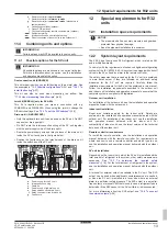
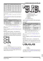
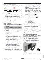
An external alarm circuit (field supply) must be connected to the SVS
output of the SV unit, see
This alarm system must warn audibly AND visibly (e.g. a loud buzzer
AND a flashing light). The audible alarm must be 15 dBA above the
background sound level at all times.
At least one alarm must be installed in the occupied space in which
the SV unit is installed.
For the occupancy listed below, the alarm system must
additionally
warn at a supervised location with 24-hour monitoring:
▪ with sleeping facilities.
▪ where an uncontrolled number of people are present.
▪ accessible for persons not familiar with the necessary safety
precautions.
To warn at a supervised location, connect a supervisor remote
controller to the system. This supervisor remote controller can be
connected to any indoor unit of the system, and will warn at the
supervised location in case a refrigerant leak is detected in any SV
unit of the system.
Note:
An address number for the supervisor
remote controller must be assigned to the SV unit. See
37].
When the R32 sensor in the SV unit detects a refrigerant leak, the
SVS output will close and activate the alarm. An error message will
display on the remote controllers of the connected indoor units. See
44].
Field settings
External alarm
Code
Description
Value
[2-0]
(a)
Cluster indication
0 (default): disable
[2-4]
(b)
Safety measures
1 (default): enable
[2-7]
(b)
Ventilated enclosure
0: disable
(a)
Set on ALL main PCBs (A1P and A2P) of the SV unit.
(b)
Set ONLY on the LEFTMOST main PCB (A1P) of the SV unit.
Note:
SV unit test run
Before SV unit operation, it is required to perform a test run that
simulates a refrigerant leak. See
41] for
more details.
12.4.3
Natural ventilation
Natural ventilation is a safety measure where ventilation is made to a
place where sufficient air is available to dilute the leaked refrigerant
such as a large space.
The duct connection must be replaced with the duct closing plate
accessory (see
"13.5.2 To install the duct closing plate"
27]).
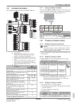
The natural ventilation safety measure can be applied by following
the steps below:
Step 1
– Determine total room area, which is the total area of the
space that has natural ventilation
and
the space in which the SV unit
is installed:
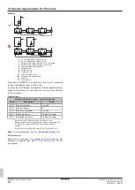
The respective room area can be determined by projecting the walls,
doors and partitions to the floor and calculating the enclosed area.
Spaces connected only through false ceilings, ductwork, or similar
connections are not considered a single space.
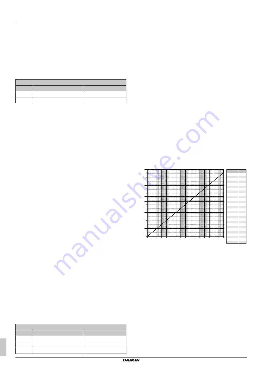
Step 2
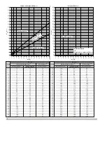
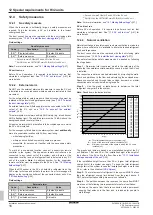
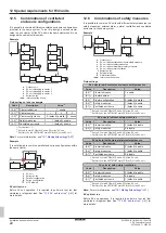
– Use the graph or table below to determine the total
refrigerant charge limit in the system:
Note:
Round down the derived values.
0
10
20
30
40
50
60
70
80
90
100
110
120
130
140
150
160
170
180
190
200
210
220
230
240
250
5
0
25 30 35 40 45 50 55 60 65
20
15
10
70 75 80
m
[kg]
A
1
+ A
min
[m
2
]
A
1
+ A
min
[m²]
m
[kg]
20
6.7
30
10.1
40
0
0
10
3.3
13.5
50
16.8
60
20.2
70
23.6
80
27.0
90
30.3
100
33.7
110
37.1
120
40.5
130
43.9
140
47.2
150
50.6
160
54.0
170
57.4
180
60.7
190
64.1
200
67.5
210
70.9
220
74.2
230
77.6
236
79.6
237
79.8
240
79.8
250
79.8
m
Total refrigerant charge in the system [kg]
A
1
Area of the room with natural ventilation [m²]
A
min
Minimum room area of the space in which the SV unit is
installed [m²]
The graphs and table are based on an installation height of the SV
unit between 1.8 m and 2.2 m. The installation height is the height of
the bottom of the SV unit to the floor. See also
site requirements of the unit"
23].
If the installation height is more than 2.2 m, higher total refrigerant
charge limit of the system can apply. To know the total refrigerant
charge limit of the system in case the installation height is more than
2.2 m, refer to the online tool (
).
Step 3
– The total amount of refrigerant in the system MUST be less
than the refrigerant charge limit derived from the graph above. If
NOT, natural ventilation safety measure is not allowed.
Step 4
– The partition between two rooms on the same floor MUST
meet one of the following two requirements for natural ventilation.
▪ Rooms on the same floor that are connected with a permanent
opening that extends to the floor and is intended for people to
walk through.
Summary of Contents for VRV 5
Page 47: ......

