13 Unit installation
Installation and operation manual
28
SV1ASV4~8A14AJV1B
VRV 5 safety valve unit
4P709466-1 – 2023.09
4×
PH2
SW8
≤ 3.2 N·m
13.5.3
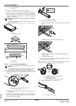
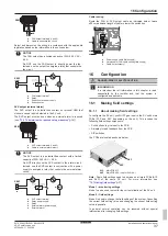
To switch the air in- and outlet side
To lower the switch box
1
25].
2
Remove the four screws.
3
Store the screws in a safe place.
4
Loosen the M8 bolts two turns without removing them.
2×
2
SW13
4×
SW8
5
Lift the switch box, pull it forward and lower it.
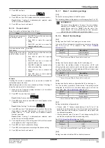
To remove the damper
1
Remove the leftmost wire fixing plate. It holds the damper wire
in place.
▪ Loosen the screws lightly without removing them.
▪ Slide and lift the plate.
2×
PH2
SW8
1
2
1
2
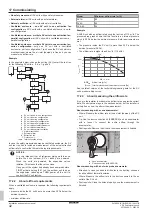
Loosen the damper wires in the switch box:
▪ Cut the cable tie that fixes the connector.
▪ Unplug the damper wire from the connector.
▪ Loosen and remove the damper earth wire screw and
detach the damper earth wire.
▪ Store the screw in a safe place.
a
c
1×
PH2
b
d
a
Connector
b
Earth wire screw
c
Damper earth wire
d
Cable tie
3
Cut the cable ties that fix the damper wire to the pipe, and the
one that bundles the damper wire.
b
a
b
b
a
Damper wire
b
Cable tie
4
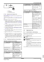
Remove the damper:
▪ Remove the four screws.
▪ Store the screws in a safe place.
▪ Pull the damper from the unit. Do not use excessive force,
as the wires on the back of the damper can get stuck inside
the unit.
▪ Carefully guide the wires from the inside to the outside
through the small hole in the unit's metal plate. Take care
not to damage the connector and the earth wire connection.
Summary of Contents for VRV 5
Page 47: ......

