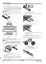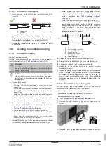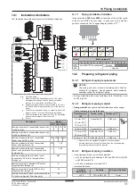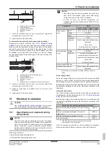
16 Configuration
Installation and operation manual
39
SV1ASV4~8A14AJV1B
VRV 5 safety valve unit
4P709466-1 – 2023.09
3
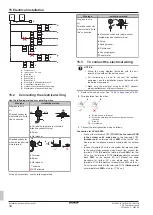
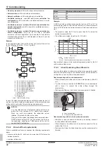
Push BS2 two times.
Result:
Mode 1 setting 2 is addressed:
4
Push BS3 one time. The displays shows the software version.
Result:
Mode 1 setting 2 is addressed and selected, return
value is monitored information.
5
Push BS1 one time to quit mode 1.
16.1.6
To use mode 2
Mode 2 is used to set field settings of the SV unit.
What
How
Changing and accessing
the setting in mode 2
▪ Push BS1 for more than five seconds
to select mode 2.
▪ Push BS2 to select the required
setting.
▪ Push BS3 one time to access the
selected setting's value.
To quit and return to the
initial status
Push BS1.
Changing the value of the
selected setting in mode 2
▪ Push BS1 for more than five seconds
to select mode 2.
▪ Push BS2 to select the required
setting.
▪ Push BS3 one time to access the
selected setting's value.
▪ Push BS2 to select the required value
of the selected setting.
▪ Push BS3 one time to validate the
change.
▪ Push BS3 again to start operation
with the chosen value.
Example
Checking the content of parameter [2‑7] (to enable or disable the
ventilated enclosure function).
[Mode‑Setting]=Value in this case is defined as: Mode=2; Setting=7;
Value=the value we want to know/change.
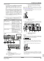
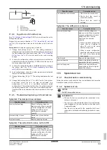
1
Make sure the 7‑segment display indication is in the default
situation (normal operation).
2
Push BS1 for more than five seconds.
Result:
Mode 2 is accessed:
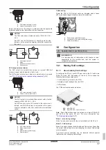
3
Push BS2 seven times (or push BS2 until seven appears on the
7‑segment display).
Result:
Mode 2 setting 7 is addressed:
4
Push BS3 one time. The display shows the status of the setting
(depending on the actual field situation). In the case of [2‑7], the
default value is "1", which means the ventilated enclosure
function is enabled.
Result:
Mode 2 setting 7 is addressed and selected, return
value is the current setting situation.
5
To change the value of the setting, push BS2 until the required
value appears on the 7‑segment display.
6
Push BS3 one time to validate the change.
7
Push BS3 to start operation according to the chosen setting.
8
Push BS1 one time to quit mode 2.
16.1.7
Mode 1: monitoring settings
[1-0]
Shows the remaining lifetime of the R32 sensor.
The remaining lifetime is displayed in months ranging from 0 to 120.
INFORMATION
The sensor has a lifetime of 10 years. The user interface
displays error "
CH-22
" 6 months before the end of the
sensor lifetime and error "
CH-23
" after the end of the
sensor lifetime. For more information, see the reference
guide of the user interface and contact your dealer.
16.1.8
Mode 2: field settings
[2-0]
Setting to define if the SV unit belongs to a cluster or not.
In case the SV unit belongs to a parallel or series cluster, this setting
has to be put on "1" to enable it. See
[2-0]
(a)
Description
0 (default)
Cluster disabled
1
Cluster enabled
(a)
Set on ALL main PCBs (A1P and A2P) of the SV unit.
[2-1]
Setting to define the cluster number the SV unit belongs to.
In case there are multiple clusters in the system, all SV units
belonging to the same cluster need to have the same cluster number
as value for this setting. SV units belonging to different clusters need
to have a different cluster number.
[2-1]
(a)
Description
0 (default)~63
Cluster number
(a)
Set on ALL main PCBs (A1P and A2P) of the SV unit.
[2-2]
Setting to define the cluster configuration the SV unit belongs to.
This can be either a parallel or series cluster. This setting must be
configured for all SV units in the same cluster, and has to be the
same value. See
17].
[2-2]
(a)
Description
0 (default)
Parallel cluster
1
Series cluster
(a)
Set on ALL main PCBs (A1P and A2P) of the SV unit.
[2-3]
Setting to simulate a refrigerant leak.
▪ Choose value "1" during commissioning of the SV unit. This
activates the safety measures of the SV unit and confirms that the
safety measures are working as intended and are conform with
the applicable legislation.
▪ After confirmation, reset it to value "0" and change setting [2-6] to
confirm the completion of the commissioning check.
See
"17.2.1 About the SV unit test run"
41].
[2-3]
(a)
Simulate refrigerant leak
0 (default)
OFF
1
ON
(a)
Set ONLY on the LEFTMOST main PCB (A1P) of the SV unit.
[2-4]
Setting to enable or disable all SV unit safety measures.
Summary of Contents for VRV 5
Page 47: ......


