23 Glossary
Installation and operation manual
46
SV1ASV4~8A14AJV1B
VRV 5 safety valve unit
4P709466-1 – 2023.09
Symbol
Meaning
S*PL
Pressure switch (low)
S*T
Thermostat
S*RH
Humidity sensor
S*W, SW*
Operation switch
SA*, F1S
Surge arrester
SEG*
7-segment display
SR*, WLU
Signal receiver
SS*
Selector switch
SHEET METAL
Terminal strip fixed plate
T*R
Transformer
TC, TRC
Transmitter
V*, R*V
Varistor
V*R
Diode bridge, Insulated-gate bipolar
transistor (IGBT) power module
WRC
Wireless remote controller
X*
Terminal
X*M
Terminal strip (block)
X*Y
Connector
Y*E
Electronic expansion valve coil
Y*R, Y*S
Reversing solenoid valve coil
Z*C
Ferrite core
ZF, Z*F
Noise filter
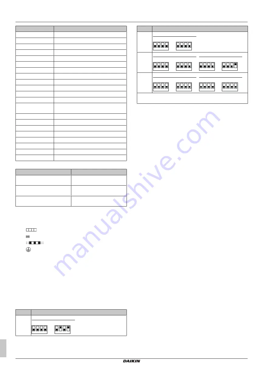
Specific SV unit wiring diagram legend
Symbol
Meaning
EVSG
Electronic expansion valve (gas
shut-off valve)
EVSL
Electronic expansion valve (liquid
shut-off valve)
X15A
Connector (drain up kit abnormal
signal)
Notes
1
This wiring diagram applies to the SV unit only.
2
Symbols:
: terminal block
: connector
: field wiring
: earth terminal
3
For wiring for the terminal block on X2M ~ X6M (operation),
see the installation manual attached to the product.
4
For X15A (A1P), remove the short circuit connector and
connect the air conditioner stop signal (optional product)
when using the drain up kit (optional product). For details, see
the operation manual attached to the kit.
5
The capacity of the contact is 220~240V AC-0.5A.
6
Digital output: max 220~240V AC-0.5A. To use this output,
see the installation manual.
7
The factory settings of DIP switch (DS1, DS2) are as follows:
Model
DS1, DS2 factory settings
SV1A
ON
DS1
A1P
OFF
1 2 3 4
ON
DS2
OFF
1 2 3 4
Model
DS1, DS2 factory settings
SV4A
ON
DS1
A1P
OFF
1 2 3 4
ON
DS2
OFF
1 2 3 4
SV6A
ON
DS1
A1P
OFF
1 2 3 4
ON
DS2
OFF
1 2 3 4
ON
DS1
A2P
OFF
1 2 3 4
ON
DS2
OFF
1 2 3 4
SV8A
ON
DS1
A1P
OFF
1 2 3 4
ON
DS2
OFF
1 2 3 4
ON
DS1
A2P
OFF
1 2 3 4
ON
DS2
OFF
1 2 3 4
To set the DIP switches (DS1~2) and push buttons (BS1~3), see
the installation manual
23
Glossary
Dealer
Sales distributor for the product.
Authorised installer
Technical skilled person who is qualified to install the
product.
User
Person who is owner of the product and/or operates the
product.
Applicable legislation
All international, European, national and local directives,
laws, regulations and/or codes that are relevant and
applicable for a certain product or domain.
Service company
Qualified company which can perform or coordinate the
required service to the product.
Installation manual
Instruction manual specified for a certain product or
application, explaining how to install, configure and maintain
it.
Operation manual
Instruction manual specified for a certain product or
application, explaining how to operate it.
Maintenance instructions
Instruction manual specified for a certain product or
application, which explains (if relevant) how to install,
configure, operate and/or maintain the product or
application.
Accessories
Labels, manuals, information sheets and equipment that are
delivered with the product and that need to be installed
according to the instructions in the accompanying
documentation.
Optional equipment
Equipment made or approved by Daikin that can be
combined with the product according to the instructions in
the accompanying documentation.
Field supply
Equipment NOT made by Daikin that can be combined with
the product according to the instructions in the
accompanying documentation.
Summary of Contents for VRV 5
Page 47: ......


