Specifications
Si39-306
40
Specifications
1.3
BS Units
Note:
+
1 If the total capacity of all indoor units connected to the system is less than 7.1 kW, connect the attached pipe to the field pipe.
(Braze the connection between the attached pipe and field pipe.)
+
2 Use the field flanged pipe.
Also, with a 200 class indoor unit, connect the attached reducer to the field pipe. (Braze the connection between the attached pipe and
field pipe.)
3 The indoor unit size of 20.25.32.40 can not be connected to BSVQ250MV1.
Connection Range for BS Unit
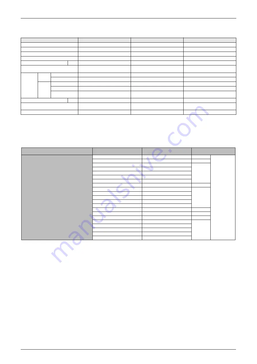
Model
BSVQ100MV1
BSVQ160MV1
BSVQ250MV1
Power Supply
1 Phase 50Hz 220~240V
1 Phase 50Hz 220~240V
1 Phase 50Hz 220~240V
Total Capacity Index of Indoor Unit
Less than 100
100 or more but less than 160
160 or more but 250 or less
No. of Connectable Indoor Units
Max. 5
Max. 8
Max. 8
Casing
Galvanized Steel Plate
Galvanized Steel Plate
Galvanized Steel Plate
Dimensions: (H×W×D)
mm
185×310×280
185×310×280
185×310×280
Sound Absorbing Thermal Insulation
Material
Flame and Heat Resistant Foamed
Polyethylene
Flame and Heat Resistant Foamed
Polyethylene
Flame and Heat Resistant Foamed
Polyethylene
Piping
Connection
Indoor
Unit
Liquid Pipes
φ
9.5mm (Flare Connection)
+
1
φ
9.5mm (Flare Connection)
φ
9.5mm (Flare Connection)
Gas Pipes
φ
15.9mm (Flare Connection)
+
1
φ
15.9mm (Flare Connection)
φ
22.2mm (Flange Connection)
+
2
Outdoor
Unit
Liquid Pipes
φ
9.5mm (Flare Connection)
+
1
φ
9.5mm (Flare Connection)
φ
9.5mm (Flare Connection)
Suction Gas Pipes
φ
15.9mm (Flare Connection)
+
1
φ
15.9mm (Flare Connection)
φ
22.2mm (Flange Connection)
+
2
Discharge Gas
Pipes
φ
12.7mm (Flare Connection)
+
1
φ
12.7mm (Flare Connection)
19.1mm (Flare Connection)
Weight
kg
9
9
10
Standard Accessories
Installation Manual, Attached Pipe,
Insulation pipe cover, Clamps
Installation Manual, Insulation pipe
cover, Clamps
Installation Manual, Attached Pipe,
Insulation pipe cover Clamps.
Drawing No.
4D042118
4D042119
4D042120
REYQ16M
200 to 520
20
16
22
13
34
36
38
40
Same number of
BS units
REYQ18M
225 to 585
REYQ8M
100 to 260
REYQ10M
125 to 325
REYQ12M
150 to 390
REYQ14M
178 to 461
REYQ20M
REYQ22M
250 to 650
REYQ24M
275 to 715
32
REYQ26M
REYQ28M
REYQ30M
Indoor unit total capacity
Outdoor unit/BS unit
model name
Total capacity of connectable indoor
units
Number of connectable
indoor units
Components
303 to 786
325 to 845
350 to 910
REYQ36M
428 to 1,111
REYQ38M
450 to 1,170
REYQ32M
378 to 981
REYQ34M
400 to 1,040
REYQ40M
475 to 1,235
REYQ42M
505 to 1,313
REYQ44M
REYQ46M
REYQ48M
525 to 1,365
550 to 1,430
580 to 1,508
600 to 1,560
Summary of Contents for VRV II REYQ10MY1B
Page 19: ...Model Selection Si39 306 8 General Information ...
Page 150: ...Si39 306 Troubleshooting by Remote Controller Troubleshooting 139 ...
Page 250: ...Si39 306 Piping Diagrams Appendix 239 REYQ14MY1B REYQ16MY1B 4D042070A ...
Page 252: ...Si39 306 Piping Diagrams Appendix 241 1 3 BS Unit BSVQ100MV1 BSVQ160MV1 BSVQ250MV1 4D042115 ...
Page 254: ...Si39 306 Wiring Diagrams for Reference Appendix 243 REYQ14MY1B REYQ16MY1B 3D038572 ...
Page 256: ...Si39 306 Wiring Diagrams for Reference Appendix 245 REYQ18 20 22 24 26 28 30 32MY1B 3D043436 ...
Page 257: ...Wiring Diagrams for Reference Si39 306 246 Appendix REYQ34 36 38 40 42 44 46 48MY1B 3D043437 ...
Page 259: ...Wiring Diagrams for Reference Si39 306 248 Appendix FXCQ40M 50M 80M 125MVE 3D039557A ...
Page 260: ...Si39 306 Wiring Diagrams for Reference Appendix 249 FXZQ20M 25M 32M 40M 50MVE 3D038359 ...
Page 262: ...Si39 306 Wiring Diagrams for Reference Appendix 251 FXKQ25M 32M 40M 63MVE 3D039564A ...
Page 264: ...Si39 306 Wiring Diagrams for Reference Appendix 253 FXMQ40M 50M 63M 80M 100M 125MVE 3D039620A ...
Page 265: ...Wiring Diagrams for Reference Si39 306 254 Appendix FXMQ200M 250MVE 3D039621A ...
Page 266: ...Si39 306 Wiring Diagrams for Reference Appendix 255 FXHQ32M 63M 100MVE 3D039801C ...
Page 267: ...Wiring Diagrams for Reference Si39 306 256 Appendix FXAQ20M 25M 32MVE 40M 50M 63MVE 3D034206A ...
Page 283: ...REFNET Pipe System Si39 306 272 Appendix ...
Page 284: ...Si39 306 Appendix 273 DPSOH RI RQQHFWLRQ 5 7 SH 5 4 0 HDW 5HFRYHU ...
Page 285: ...Si39 306 274 Appendix ...
Page 291: ...Method of Replacing The Inverter s Power Transistors and Diode Modules Si39 306 280 Appendix ...
Page 305: ...Si39 306 iv Index ...


