Si39-502A
Field Setting
Test Operation
99
3.1.6 Detailed Explanation of Setting Modes
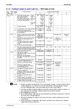
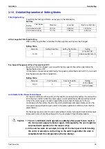
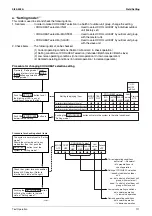
Filter Sign Setting
If switching the filter sign ON time, set as given in the table below.
Set Time
Ultra-Long-Life Filter Sign Setting
When a Ultra-long-life filter is installed, the filter sign timer setting must be changed.
Setting Table
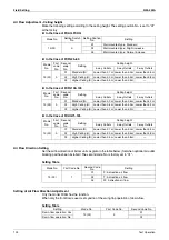
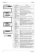
Fan Speed Changeover When Thermostat is OFF
By setting to “Set Fan Speed,” you can switch the fan speed to the set fan speed when the
heating thermostat is OFF.
∗
Since there is concern about draft if using “fan speed up when thermostat is OFF,” you should
take the setup location into consideration.
Setting Table
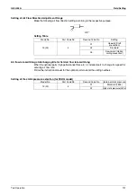
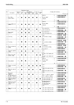
Auto Restart after Power Failure Reset
For the air conditioners with no setting for the function (same as factory setting), the units will be
left in the stop condition when the power supply is reset automatically after power failure reset
or the main power supply is turned on again after once turned off. However, for the air
conditioners with the setting, the units may start automatically after power failure reset or the
main power supply turned on again (return to the same operation condition as that of before
power failure).
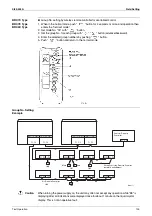
For the above reasons, when the unit is set enabling to utilize “Auto restart function after power
failure reset”, utmost care should be paid for the occurrence of the following situation.
Filter Specs.
Setting
Standard
Long Life
Ultra Long Life Filter
Contamination Light
200 hrs.
2,500 hrs.
10,000 hrs.
Contamination Heavy
100 hrs.
1,250 hrs.
5,000 hrs.
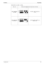
Mode No.
Setting Switch No.
Setting Position No.
Setting
10 (20)
1
01
Long-Life Filter
02
Ultra-Long-Life Filter (1)
03
—
Mode No.
First Code No.
Second Code No.
Setting
12(22)
3
01
LL Fan Speed
02
Set Fan Speed
Caution 1. The air conditioner starts operation suddenly after power failure reset or
the main power supply turned on again. Consequently, the user might be
surprised (with question for the reason why).
2. In the service work, for example, turning off the main power switch during
the unit is in operation, and turning on the switch again after the work is
completed start the unit operation (the fan rotates).
Summary of Contents for VRV II RXYQ8MY1K
Page 53: ...Specifications Si39 502A 42 Specifications...
Page 143: ...Field Setting Si39 502A 132 Test Operation...
Page 258: ...Si39 502A Wiring Diagrams for Reference Appendix 247 FXCQ40M 50M 80M 125MVE 3D039557A...
Page 260: ...Si39 502A Wiring Diagrams for Reference Appendix 249 FXKQ25M 32M 40M 63MVE 3D039564A...
Page 264: ...Si39 502A Wiring Diagrams for Reference Appendix 253 FXMQ40M 50M 63M 80M 100M 125MVE 3D039620A...
Page 265: ...Wiring Diagrams for Reference Si39 502A 254 Appendix FXMQ200M 250MVE 3D039621A...
Page 266: ...Si39 502A Wiring Diagrams for Reference Appendix 255 FXHQ32M 63M 100MVE 3D039801C...
Page 267: ...Wiring Diagrams for Reference Si39 502A 256 Appendix FXAQ20M 25M 32M 40M 50M 63MVE 3D034206A...
Page 269: ...Wiring Diagrams for Reference Si39 502A 258 Appendix FXUQ71M 100M 125MV1 3D044973...
Page 270: ...Si39 502A Wiring Diagrams for Reference Appendix 259 FXAQ20MH 25MH 32MH 40MH 50MHV1 3D046348A...
Page 271: ...Wiring Diagrams for Reference Si39 502A 260 Appendix FXLQ20MH 25MH 32MH 40MH 50MHV1 3D046787A...
Page 272: ...Si39 502A Wiring Diagrams for Reference Appendix 261 BEVQ50MVE 3D046579A Notes...
Page 273: ...Wiring Diagrams for Reference Si39 502A 262 Appendix BEVQ71M 100M 125MVE 3D044901A Notes...
Page 285: ...Piping Installation Point Si39 502A 274 Appendix...
Page 293: ...Method of Replacing The Inverter s Power Transistors and Diode Modules Si39 502A 282 Appendix...
Page 307: ...Si39 502A iv Index...

