Si39-502A
134
Troubleshooting
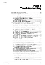
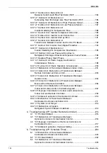
” Outdoor Unit: Malfunction of
Receiver Outlet Liquid Pipe Thermistor (R6T) .....................................184
” Outdoor Unit: Malfunction of
Subcooling Heat Exchanger Gas Pipe Thermistor (R5T).....................185
” Outdoor Unit: Malfunction of High Pressure Sensor......................186
” Outdoor Unit: Malfunction of Low Pressure Sensor.......................187
” Outdoor Unit: Malfunction of
Inverter Radiating Fin Temperature Rise .............................................188
” Outdoor Unit: Inverter Compressor Abnormal ...............................189
” Outdoor Unit: Inverter Current Abnormal .......................................190
” Outdoor Unit: Inverter Start up Error..............................................191
” Outdoor Unit: Malfunction of
Transmission Between Inverter and Control PC Board........................192
” Outdoor Unit: Inverter Over-Ripple Protection ...............................194
” Outdoor Unit: Malfunction of
Inverter Radiating Fin Temperature Rise Sensor.................................195
” Outdoor Unit: Low Pressure Drop Due to
Refrigerant Shortage or Electronic Expansion Valve Failure ...............196
” Reverse Phase, Open Phase.........................................................197
” Outdoor Unit: Power Supply Insufficient or
Instantaneous Failure...........................................................................198
” Outdoor Unit: Check Operation not executed................................200
” Malfunction of Transmission Between Indoor Units ......................201
” Indoor Unit: Malfunction of Transmission Between
Remote Controller and Indoor Unit.......................................................203
” Indoor Unit: Malfunction of Transmission Between
” Indoor Unit: Malfunction of Transmission Between
Main and Sub Remote Controllers .......................................................206
” Indoor Unit: Malfunction of Transmission Between
Indoor and Outdoor Units in the Same System....................................207
” Improper Combination of Indoor and Outdoor Units,
Indoor Unit and Remote Controller.......................................................209
” Address Duplication of Centralized Controller ...............................210
” Malfunction of Transmission Between
Centralized Controller and Indoor Unit .................................................211
” System is not Set yet .....................................................................213
Refrigerant System Address Undefined ...............................................214
4. Troubleshooting (OP: Central Remote Controller) ..............................215
” PC Board Defect ............................................................................215
” Malfunction of Transmission Between
Optional Controllers for Centralized Control.........................................216
” Improper Combination of Optional Controllers for
” Address Duplication, Improper Setting ..........................................219
5. Troubleshooting (OP: Schedule Timer)...............................................220
” Malfunction of Transmission Between
Centralized Controller and Indoor Unit .................................................220
” PC Board Defect ............................................................................222
” Malfunction of Transmission Between
Optional Controllers for Centralized Control.........................................223
Summary of Contents for VRV II RXYQ8MY1K
Page 53: ...Specifications Si39 502A 42 Specifications...
Page 143: ...Field Setting Si39 502A 132 Test Operation...
Page 258: ...Si39 502A Wiring Diagrams for Reference Appendix 247 FXCQ40M 50M 80M 125MVE 3D039557A...
Page 260: ...Si39 502A Wiring Diagrams for Reference Appendix 249 FXKQ25M 32M 40M 63MVE 3D039564A...
Page 264: ...Si39 502A Wiring Diagrams for Reference Appendix 253 FXMQ40M 50M 63M 80M 100M 125MVE 3D039620A...
Page 265: ...Wiring Diagrams for Reference Si39 502A 254 Appendix FXMQ200M 250MVE 3D039621A...
Page 266: ...Si39 502A Wiring Diagrams for Reference Appendix 255 FXHQ32M 63M 100MVE 3D039801C...
Page 267: ...Wiring Diagrams for Reference Si39 502A 256 Appendix FXAQ20M 25M 32M 40M 50M 63MVE 3D034206A...
Page 269: ...Wiring Diagrams for Reference Si39 502A 258 Appendix FXUQ71M 100M 125MV1 3D044973...
Page 270: ...Si39 502A Wiring Diagrams for Reference Appendix 259 FXAQ20MH 25MH 32MH 40MH 50MHV1 3D046348A...
Page 271: ...Wiring Diagrams for Reference Si39 502A 260 Appendix FXLQ20MH 25MH 32MH 40MH 50MHV1 3D046787A...
Page 272: ...Si39 502A Wiring Diagrams for Reference Appendix 261 BEVQ50MVE 3D046579A Notes...
Page 273: ...Wiring Diagrams for Reference Si39 502A 262 Appendix BEVQ71M 100M 125MVE 3D044901A Notes...
Page 285: ...Piping Installation Point Si39 502A 274 Appendix...
Page 293: ...Method of Replacing The Inverter s Power Transistors and Diode Modules Si39 502A 282 Appendix...
Page 307: ...Si39 502A iv Index...


