Si39-502A
Piping Installation Point
Appendix
273
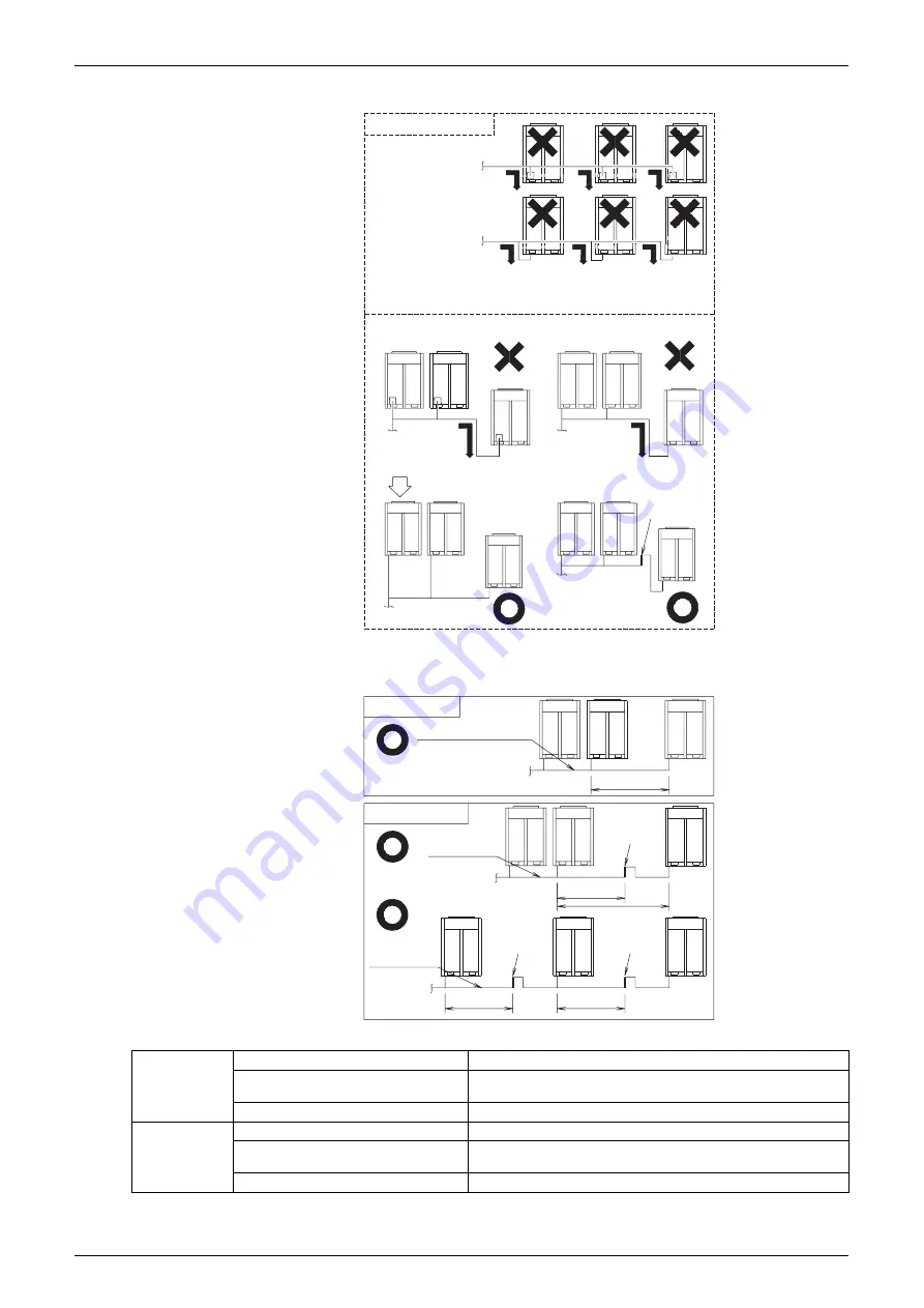
1. If the piping length between the outdoor unit-connecting pipe kits or between the outdoor
units exceeds 2 m, create a rise of 200 mm or more in the gas line within a length of 2 m
from the kit.
Note:
Refer to page 276 Note 2 in case of up to 90m.
Prohibited pattern
to indoor unit
to indoor unit
Oil remains in the stopping outdoor unit.
Change to pattern 1 or pattern 2
Unit A
Unit B
Unit C
Unit C
Unit A
Unit B
to indoor unit
Change as shown in the figure below.
to indoor unit
to indoor unit
to indoor unit
Oil remains in the outdoor unit C when the system stops.
Rising height:
200 mm or more
to indoor
unit
If 2 m or less
If 2 m or more
Piping between outdoor units
Piping between
outdoor units
Piping between
outdoor units
to indoor unit
2m or less
2m or less
2m
or more
Rising height:
200 mm or more
Rising height:
200 mm or more
Rising height:
200 mm or more
2m or less
2m or less
Max.allowable
Piping Length
Outdoor Unit - Multi Connection Piping Kit Actual piping length 10m or less, equivalent length 13m or less
Multi Connection Piping Kit - Indoor Unit
Actual piping length 150m or less, equivalent length 175m or less,
the total extension 510m or less
REFNET Joint - Indoor Unit
Actual piping length 40(90)m or less
Note
Allowable Level
Difference
Outdoor Unit - Outdoor Unit
5m or less
Outdoor Unit - Indoor Unit
50m or less
(when an outdoor unit is lower than indoor units : 40m or less)
Indoor Unit - Indoor Unit
15m or less
Summary of Contents for VRV II RXYQ8MY1K
Page 53: ...Specifications Si39 502A 42 Specifications...
Page 143: ...Field Setting Si39 502A 132 Test Operation...
Page 258: ...Si39 502A Wiring Diagrams for Reference Appendix 247 FXCQ40M 50M 80M 125MVE 3D039557A...
Page 260: ...Si39 502A Wiring Diagrams for Reference Appendix 249 FXKQ25M 32M 40M 63MVE 3D039564A...
Page 264: ...Si39 502A Wiring Diagrams for Reference Appendix 253 FXMQ40M 50M 63M 80M 100M 125MVE 3D039620A...
Page 265: ...Wiring Diagrams for Reference Si39 502A 254 Appendix FXMQ200M 250MVE 3D039621A...
Page 266: ...Si39 502A Wiring Diagrams for Reference Appendix 255 FXHQ32M 63M 100MVE 3D039801C...
Page 267: ...Wiring Diagrams for Reference Si39 502A 256 Appendix FXAQ20M 25M 32M 40M 50M 63MVE 3D034206A...
Page 269: ...Wiring Diagrams for Reference Si39 502A 258 Appendix FXUQ71M 100M 125MV1 3D044973...
Page 270: ...Si39 502A Wiring Diagrams for Reference Appendix 259 FXAQ20MH 25MH 32MH 40MH 50MHV1 3D046348A...
Page 271: ...Wiring Diagrams for Reference Si39 502A 260 Appendix FXLQ20MH 25MH 32MH 40MH 50MHV1 3D046787A...
Page 272: ...Si39 502A Wiring Diagrams for Reference Appendix 261 BEVQ50MVE 3D046579A Notes...
Page 273: ...Wiring Diagrams for Reference Si39 502A 262 Appendix BEVQ71M 100M 125MVE 3D044901A Notes...
Page 285: ...Piping Installation Point Si39 502A 274 Appendix...
Page 293: ...Method of Replacing The Inverter s Power Transistors and Diode Modules Si39 502A 282 Appendix...
Page 307: ...Si39 502A iv Index...


