Special Control
Si39-502A
64
Function
3.4
Pump-down Residual Operation
3.4.1 Pump-down Residual Operation in Cooling Operation
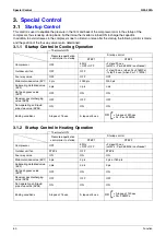
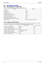
If the liquid refrigerant stays in the heat exchanger at the startup of a compressor, this liquid refrigerant enters the
compressor, thus resulting in diluted oil in the compressor and then degraded lubrication performance.
Consequently, in order to recover the refrigerant in the heat exchanger while the compressor stops, the pump-down
residual operation is conducted.
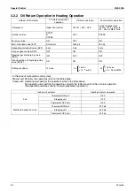
3.4.2 Pump-down Residual Operation in Heating Operation
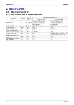
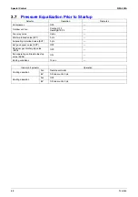
Actuator
Master unit operation
Slave unit operation
Compressor
210 Hz + OFF + OFF
OFF
Outdoor unit fan
Fan control
OFF
Four way valve
OFF
OFF
Main motorized valve (EV1)
2000 pls
0 pls
Subcooling motorized valve (EV2)
0 pls
0 pls
Hot gas bypass valve (SVP)
ON
OFF
Receiver gas discharging valve (SVG)
OFF
OFF
Non-operating unit liquid pipe stop
valve (SVSL)
ON
ON
Ending conditions
•
5 min.
•
Pe<0.49 MPa
•
Td>110
°
C
or
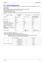
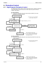
Actuator
Master unit operation
Slave unit operation
Compressor
124 Hz + OFF + OFF
OFF
Outdoor unit fan
STEP7
STEP4
Four way valve
ON
ON
Main motorized valve (EV1)
0 pls
0 pls
Subcooling motorized valve (EV2)
0 pls
0 pls
Hot gas bypass valve (SVP)
ON
OFF
Receiver gas discharging valve (SVG)
OFF
OFF
Non-operating unit liquid pipe stop
valve (SVSL)
ON
ON
Ending conditions
•
30 sec.
•
Pe<0.25 MPa
•
Td>110
°
C
or
Summary of Contents for VRV II RXYQ8MY1K
Page 53: ...Specifications Si39 502A 42 Specifications...
Page 143: ...Field Setting Si39 502A 132 Test Operation...
Page 258: ...Si39 502A Wiring Diagrams for Reference Appendix 247 FXCQ40M 50M 80M 125MVE 3D039557A...
Page 260: ...Si39 502A Wiring Diagrams for Reference Appendix 249 FXKQ25M 32M 40M 63MVE 3D039564A...
Page 264: ...Si39 502A Wiring Diagrams for Reference Appendix 253 FXMQ40M 50M 63M 80M 100M 125MVE 3D039620A...
Page 265: ...Wiring Diagrams for Reference Si39 502A 254 Appendix FXMQ200M 250MVE 3D039621A...
Page 266: ...Si39 502A Wiring Diagrams for Reference Appendix 255 FXHQ32M 63M 100MVE 3D039801C...
Page 267: ...Wiring Diagrams for Reference Si39 502A 256 Appendix FXAQ20M 25M 32M 40M 50M 63MVE 3D034206A...
Page 269: ...Wiring Diagrams for Reference Si39 502A 258 Appendix FXUQ71M 100M 125MV1 3D044973...
Page 270: ...Si39 502A Wiring Diagrams for Reference Appendix 259 FXAQ20MH 25MH 32MH 40MH 50MHV1 3D046348A...
Page 271: ...Wiring Diagrams for Reference Si39 502A 260 Appendix FXLQ20MH 25MH 32MH 40MH 50MHV1 3D046787A...
Page 272: ...Si39 502A Wiring Diagrams for Reference Appendix 261 BEVQ50MVE 3D046579A Notes...
Page 273: ...Wiring Diagrams for Reference Si39 502A 262 Appendix BEVQ71M 100M 125MVE 3D044901A Notes...
Page 285: ...Piping Installation Point Si39 502A 274 Appendix...
Page 293: ...Method of Replacing The Inverter s Power Transistors and Diode Modules Si39 502A 282 Appendix...
Page 307: ...Si39 502A iv Index...


