Si39-502A
Precautions for New Refrigerant (R-410A)
Precautions for New Refrigerant (R-410A)
287
1.3
Service Tools
R-410A is used under higher working pressure, compared to previous refrigerants (R-22,
R-407C). Furthermore, the refrigerating machine oil has been changed from Suniso oil to Ether
oil, and if oil mixing is occurred, sludge results in the refrigerants and causes other problems.
Therefore, gauge manifolds and charge hoses that are used with a previous refrigerant (R-22,
R-407C) can not be used for products that use new refrigerants.
Be sure to use dedicated tools and devices.
Tool compatibility
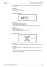
As for the charge mouthpiece and packing, 1/2UNF20 is necessary for mouthpiece size of
charge hose.
Copper tube material and thickness
* O: Soft (Annealed)
H: Hard (Drawn)
Tool
Compatibility
Reasons for change
HFC
HCFC
R-410A
R-407C
R-22
Gauge manifold
Charge hose
✕
2
Do not use the same tools for R-22
and R-410A.
2
Thread specification differs for
R-410A and R-407C.
Charging cylinder
✕
{
2
Weighting instrument used for HFCs.
Gas detector
{
✕
2
The same tool can be used for HFCs.
Vacuum pump
(pump with reverse flow
preventive function)
{
2
To use existing pump for HFCs,
vacuum pump adaptor must be
installed.
Weighting instrument
{
Charge mouthpiece
✕
2
Seal material is different between
R-22 and HFCs.
2
Thread specification is different
between R-410A and others.
Flaring tool (Clutch type)
{
2
For R-410A, flare gauge is necessary.
Torque wrench
{
2
Torque-up for 1/2 and 5/8
Pipe cutter
{
Pipe expander
{
Pipe bender
{
Pipe assembling oil
✕
2
Due to refrigerating machine oil
change. (No Suniso oil can be used.)
Refrigerant recovery
device
Check your recovery device.
Refrigerant piping
See the chart below.
2
Only
φ
19.1 is changed to 1/2H material
while the previous material is "O".
Pipe size
φ
6.4
φ
9.5
φ
12.7
φ
15.9
φ
19.1
φ
22.2
φ
25.4
φ
28.6
φ
31.8
φ
38.1
φ
44.5
Ve-up
R-407C
Material
O
O
O
O
O
1/2H
1/2H
1/2H
1/2H
1/2H
1/2H
Ve-up
II
R-410A
Material
O
O
O
O
1/2H
1/2H
1/2H
1/2H
1/2H
1/2H
1/2H
Thickness
t (mm)
0.8
0.8
0.8
1.0
1.0
1.0
1.0
1.0
1.2
1.4
1.6
Thickness
t (mm)
0.8
0.8
0.8
1.0
1.0
1.0
1.0
1.0
1.1
1.4
1.6
Summary of Contents for VRV II RXYQ8MY1K
Page 53: ...Specifications Si39 502A 42 Specifications...
Page 143: ...Field Setting Si39 502A 132 Test Operation...
Page 258: ...Si39 502A Wiring Diagrams for Reference Appendix 247 FXCQ40M 50M 80M 125MVE 3D039557A...
Page 260: ...Si39 502A Wiring Diagrams for Reference Appendix 249 FXKQ25M 32M 40M 63MVE 3D039564A...
Page 264: ...Si39 502A Wiring Diagrams for Reference Appendix 253 FXMQ40M 50M 63M 80M 100M 125MVE 3D039620A...
Page 265: ...Wiring Diagrams for Reference Si39 502A 254 Appendix FXMQ200M 250MVE 3D039621A...
Page 266: ...Si39 502A Wiring Diagrams for Reference Appendix 255 FXHQ32M 63M 100MVE 3D039801C...
Page 267: ...Wiring Diagrams for Reference Si39 502A 256 Appendix FXAQ20M 25M 32M 40M 50M 63MVE 3D034206A...
Page 269: ...Wiring Diagrams for Reference Si39 502A 258 Appendix FXUQ71M 100M 125MV1 3D044973...
Page 270: ...Si39 502A Wiring Diagrams for Reference Appendix 259 FXAQ20MH 25MH 32MH 40MH 50MHV1 3D046348A...
Page 271: ...Wiring Diagrams for Reference Si39 502A 260 Appendix FXLQ20MH 25MH 32MH 40MH 50MHV1 3D046787A...
Page 272: ...Si39 502A Wiring Diagrams for Reference Appendix 261 BEVQ50MVE 3D046579A Notes...
Page 273: ...Wiring Diagrams for Reference Si39 502A 262 Appendix BEVQ71M 100M 125MVE 3D044901A Notes...
Page 285: ...Piping Installation Point Si39 502A 274 Appendix...
Page 293: ...Method of Replacing The Inverter s Power Transistors and Diode Modules Si39 502A 282 Appendix...
Page 307: ...Si39 502A iv Index...


