Si39-502A
Special Control
Function
61
3.2
Oil Return Operation
In order to prevent the compressor from running out of oil, the oil return operation is conducted to recover oil flown out
from the compressor to the system side.
3.2.1 Oil Return Operation in Cooling Operation
[Start conditions]
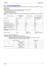
Referring to the set conditions for the following items, start the oil return operation in cooling.
• Cumulative oil feed rate
• Timer setting (Make this setting so as to start the oil return operation when the initial cumulative operating time
reaches two hours after power supply is turned ON and then every eight hours.)
Furthermore, the cumulative oil feed rate is computed from Tc, Te, and compressor loads.
∗
In the case of multi-outdoor-unit system,
Master unit: Performs the operations listed in the table above.
Slave units: Operating units perform the operations listed in the table above.
Non-operating units perform the operations listed in the table above from the oil return operation.
(Non-operating unit stops during “oil return preparation operation”.)
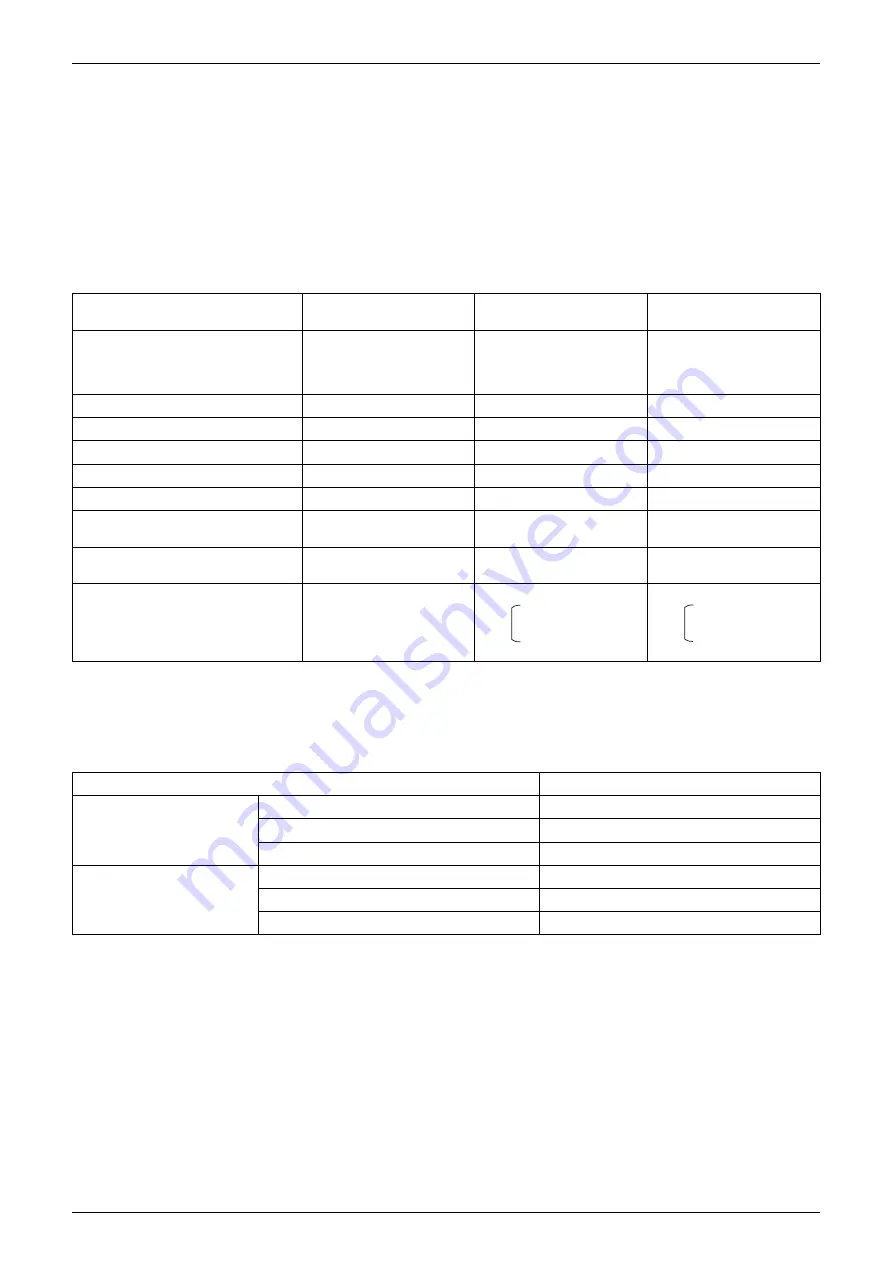
Outdoor unit actuator
Oil return preparation
operation
Oil return operation
Post-oil-return operation
Compressor
Upper limit control
177 Hz + OFF + OFF
Lapse of 20 sec.
Pe<5.5k
⇒
Inv
25 Step Down
Pe>6.5k
⇒
1 Step Up
52 Hz + OFF + OFF
Outdoor unit fan
Fan control
Fan control
Fan control
Four way valve
OFF
OFF
OFF
Main motorized valve (EV1)
2000 pls
2000 pls
2000 pls
Subcooling motorized valve (EV2)
SH control
0 pls
0 pls
Hot gas bypass valve (SVP)
OFF
ON
ON
Receiver gas discharging valve
(SVG)
OFF
OFF
OFF
Non-operating unit liquid pipe stop
valve (SVSL)
ON
ON
ON
Ending conditions
20 sec.
•
3 min.
•
Ts - Te<5
°
C
•
3 min.
•
Pe<0.4MPa
•
HTdi>110
°
C
or
or
Indoor unit actuator
Cooling oil return operation
Fan
Thermostat ON unit
Set flow rate (subject to the situation)
Stopping unit
OFF
Thermostat OFF unit
OFF
Electronic expansion valve
Thermostat ON unit
Normal opening
Stopping unit
200 pls
Thermostat OFF unit
200 pls
Summary of Contents for VRV II RXYQ8MY1K
Page 53: ...Specifications Si39 502A 42 Specifications...
Page 143: ...Field Setting Si39 502A 132 Test Operation...
Page 258: ...Si39 502A Wiring Diagrams for Reference Appendix 247 FXCQ40M 50M 80M 125MVE 3D039557A...
Page 260: ...Si39 502A Wiring Diagrams for Reference Appendix 249 FXKQ25M 32M 40M 63MVE 3D039564A...
Page 264: ...Si39 502A Wiring Diagrams for Reference Appendix 253 FXMQ40M 50M 63M 80M 100M 125MVE 3D039620A...
Page 265: ...Wiring Diagrams for Reference Si39 502A 254 Appendix FXMQ200M 250MVE 3D039621A...
Page 266: ...Si39 502A Wiring Diagrams for Reference Appendix 255 FXHQ32M 63M 100MVE 3D039801C...
Page 267: ...Wiring Diagrams for Reference Si39 502A 256 Appendix FXAQ20M 25M 32M 40M 50M 63MVE 3D034206A...
Page 269: ...Wiring Diagrams for Reference Si39 502A 258 Appendix FXUQ71M 100M 125MV1 3D044973...
Page 270: ...Si39 502A Wiring Diagrams for Reference Appendix 259 FXAQ20MH 25MH 32MH 40MH 50MHV1 3D046348A...
Page 271: ...Wiring Diagrams for Reference Si39 502A 260 Appendix FXLQ20MH 25MH 32MH 40MH 50MHV1 3D046787A...
Page 272: ...Si39 502A Wiring Diagrams for Reference Appendix 261 BEVQ50MVE 3D046579A Notes...
Page 273: ...Wiring Diagrams for Reference Si39 502A 262 Appendix BEVQ71M 100M 125MVE 3D044901A Notes...
Page 285: ...Piping Installation Point Si39 502A 274 Appendix...
Page 293: ...Method of Replacing The Inverter s Power Transistors and Diode Modules Si39 502A 282 Appendix...
Page 307: ...Si39 502A iv Index...

