Protection Control
Si39-502A
70
Function
4.2
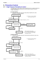
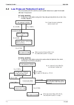
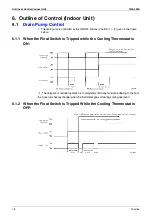
Low Pressure Protection Control
This low pressure protection control is used to protect compressors against the transient
decrease of low pressure.
[In cooling operation]
In the case of multi-outdoor-unit system, the entire system performs this control in the
following sequence.
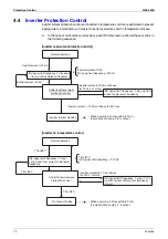
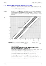
[In heating operation]
In the case of multi-outdoor-unit system, each outdoor unit performs this control
individually in the following sequence.
Low pressure not limited
Pe<0.34MPa
Low pressure standby
Low pressure limited
All STD compressors
stop.
Master unit:52 Hz + OFF + OFF
Slave unit:Stop
Pe<0.25MPa
Pe>0.39MPa
Pe<0.07MPa
Pe: LP pressure sensor detection
value for master unit
When occurring 4 times within 30 min.,
the malfunction code “ E4 ” is output.
Pe<0.17 MPa
Pe<0.13 MPa
Pe >0.23 MPa
INV upper limit frequency = 210 Hz
Pe<0.07 MPa
&
Low pressure not limited
Low pressure standby
Low pressure limited
INV upper limit frequency: 1-step /
20 sec up from current compressor
frequency
52 Hz + OFF + OFF
Pe: LP pressure sensor detection
value for each outdoor unit
Pe>0.20 MPa
Pe<0.17 MPa
When occurring 4 times within 30 min.,
the malfunction code “E4” is output.
INV upper limit frequency:
3-step down from current
compressor frequency
Summary of Contents for VRV II RXYQ8MY1K
Page 53: ...Specifications Si39 502A 42 Specifications...
Page 143: ...Field Setting Si39 502A 132 Test Operation...
Page 258: ...Si39 502A Wiring Diagrams for Reference Appendix 247 FXCQ40M 50M 80M 125MVE 3D039557A...
Page 260: ...Si39 502A Wiring Diagrams for Reference Appendix 249 FXKQ25M 32M 40M 63MVE 3D039564A...
Page 264: ...Si39 502A Wiring Diagrams for Reference Appendix 253 FXMQ40M 50M 63M 80M 100M 125MVE 3D039620A...
Page 265: ...Wiring Diagrams for Reference Si39 502A 254 Appendix FXMQ200M 250MVE 3D039621A...
Page 266: ...Si39 502A Wiring Diagrams for Reference Appendix 255 FXHQ32M 63M 100MVE 3D039801C...
Page 267: ...Wiring Diagrams for Reference Si39 502A 256 Appendix FXAQ20M 25M 32M 40M 50M 63MVE 3D034206A...
Page 269: ...Wiring Diagrams for Reference Si39 502A 258 Appendix FXUQ71M 100M 125MV1 3D044973...
Page 270: ...Si39 502A Wiring Diagrams for Reference Appendix 259 FXAQ20MH 25MH 32MH 40MH 50MHV1 3D046348A...
Page 271: ...Wiring Diagrams for Reference Si39 502A 260 Appendix FXLQ20MH 25MH 32MH 40MH 50MHV1 3D046787A...
Page 272: ...Si39 502A Wiring Diagrams for Reference Appendix 261 BEVQ50MVE 3D046579A Notes...
Page 273: ...Wiring Diagrams for Reference Si39 502A 262 Appendix BEVQ71M 100M 125MVE 3D044901A Notes...
Page 285: ...Piping Installation Point Si39 502A 274 Appendix...
Page 293: ...Method of Replacing The Inverter s Power Transistors and Diode Modules Si39 502A 282 Appendix...
Page 307: ...Si39 502A iv Index...


