Si37-701
Specifications
Specifications
11
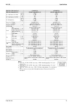
Notes:
★
1 Indoor temp. : 27°CDB, 19.5°CWB / outdoor temp. : 35°CDB / Equivalent piping length : 7.5m, level
difference : 0m.
★
2 Indoor temp. : 27°CDB, 19.0°CWB / outdoor temp. : 35°CDB / Equivalent piping length : 7.5m, level
difference : 0m.
★
3 Indoor temp. : 20°CDB / outdoor temp. : 7°CDB, 6°CWB / Equivalent piping length : 7.5m, level difference
: 0m.
4 The units with anti-corrosion treatment will be available as standard. Please specify the suffix “E” as
REYQ8PY1E.
Model Name
REYQ12PY1(E)
REYQ14PY1(E)
★
1 Cooling Capacity (19.5°CWB)
kcal / h
29,000
35,500
Btu / h
115,000
141,000
kW
33.7
41.3
★
2 Cooling Capacity (19.0°CWB)
kW
33.5
40.0
★
3 Heating Capacity
kcal / h
32,300
38,700
Btu / h
128,000
154,000
kW
37.5
45.0
Casing Color
Y1 Type
Ivory White 5Y7.5/1
Ivory White 5Y7.5/1
Y1E Type
Light Camel 2.5Y6.5/1.5
Light Camel 2.5Y6.5/1.5
Dimensions: (H×W×D)
mm
1680×1300×765
1680×1300×765
Heat Exchanger
Cross Fin Coil
Cross Fin Coil
Comp.
Type
Hermetically Sealed Scroll Type
Hermetically Sealed Scroll Type
Piston Displacement
m³/h
13.34+10.53
16.90+16.90
Number of Revolutions
r.p.m
6300, 2900
7980, 7980
Motor Output×Number
of Units
kW
3.3+4.5
3.8+3.8
Starting Method
Soft Start
Soft Start
Fan
Type
Propeller Fan
Propeller Fan
Motor Output
kW
0.35×2
0.75×2
Air Flow Rate
I/s
3,500
3,916
m³/min
210
235
Drive
Direct Drive
Direct Drive
Connecting
Pipes
Liquid Pipe
φ
12.7 C1220T (Brazing Connection)
φ
12.7 C1220T (Brazing Connection)
Suction Gas Pipe
φ
28.6 C1220T (Brazing Connection)
φ
28.6 C1220T (Brazing Connection)
High and Low Pressure Gas Pipe
φ
19.1 C1220T (Brazing Connection)
φ
22.2 C1220T (Brazing Connection)
Pressure Equalizer Tube
—
—
Mass (Weight)
kg
331
339
Safety Devices
High Pressure Switch, Fan Driver Overload Protector, Over
Current Relay, Inverter Overload Protector
High Pressure Switch, Fan Driver Overload Protector, Over
Current Relay, Inverter Overload Protector
Defrost Method
Deicer
Deicer
Capacity Control
%
14~100
10~100
Refrigerant
Refrigerant Name
R-410A
R-410A
Charge kg
10.8
11.1
Control
Electronic Expansion Valve
Electronic Expansion Valve
Refrigerator Oil
Refer to the nameplate of compressor
Refer to the nameplate of compressor
Standard Accessories
Installation Manual, Operation Manual, Connection Pipes,
Clamps
Installation Manual, Operation Manual, Connection Pipes,
Clamps
Drawing No.
4D057565
4D057566
Conversion Formulae
kcal/h=kW×860
Btu/h=kW×3412
cfm=m³/min×35.3
Summary of Contents for VRV III REYQ10PY1
Page 1: ...REYQ8 48PY1 R 410A Heat Recovery 50Hz Si37 701 ...
Page 59: ...Specifications Si37 701 48 Specifications ...
Page 105: ...Refrigerant Flow for Each Operation Mode Si37 701 94 Refrigerant Circuit ...
Page 230: ...Si37 701 Troubleshooting by Remote Controller Troubleshooting 219 ...
Page 374: ...Si37 701 Piping Diagrams Appendix 363 REYQ14P 16PY1 3D058153A S2NPL S1NPH ...
Page 375: ...Piping Diagrams Si37 701 364 Appendix REMQ8PY1 3D057743 ...
Page 376: ...Si37 701 Piping Diagrams Appendix 365 REMQ10PY1 12PY1 3D057742 ...
Page 377: ...Piping Diagrams Si37 701 366 Appendix REMQ14PY1 16PY1 3D057741 ...
Page 382: ...Si37 701 Piping Diagrams Appendix 371 1 3 BS Unit 4D057985A ...
Page 384: ...Si37 701 Wiring Diagrams for Reference Appendix 373 REYQ14 16PY1 3D056774C ...
Page 385: ...Wiring Diagrams for Reference Si37 701 374 Appendix REMQ8PY1 3D055307E ...
Page 386: ...Si37 701 Wiring Diagrams for Reference Appendix 375 REMQ10 12PY1 3D055308E ...
Page 387: ...Wiring Diagrams for Reference Si37 701 376 Appendix REMQ14P 16PY1 3D055309E ...
Page 392: ...Si37 701 Wiring Diagrams for Reference Appendix 381 FXCQ40M 50M 80M 125MVE 3D039557A ...
Page 394: ...Si37 701 Wiring Diagrams for Reference Appendix 383 FXZQ20M 25M 32M 40M 50M8V1B 3D038359 ...
Page 395: ...Wiring Diagrams for Reference Si37 701 384 Appendix FXKQ25MA 32MA 40MA 63MAVE 3D039564C ...
Page 399: ...Wiring Diagrams for Reference Si37 701 388 Appendix FXDYQ180M 200M 250MV1 ...
Page 402: ...Si37 701 Wiring Diagrams for Reference Appendix 391 FXMQ200MA 250MAVE 3D039621B ...
Page 403: ...Wiring Diagrams for Reference Si37 701 392 Appendix FXHQ32MA 63MA 100MAVE 3D039801D ...
Page 406: ...Si37 701 Wiring Diagrams for Reference Appendix 395 2 4 BS Unit 3D055928C ...
Page 423: ...Piping Installation Point Si37 701 412 Appendix ...
Page 427: ...Example of Connection R 410A Type Si37 701 416 Appendix ...
Page 433: ...Method of Checking the Inverter s Power Transistors and Diode Modules Si37 701 422 Appendix ...
Page 447: ...Si37 701 iv Index ...


