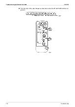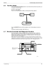
Troubleshooting by Remote Controller
Si37-701
228
Troubleshooting
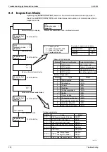
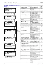
<Selection of setting item>
<Monitor mode>
<Confirmation of malfunction 1>
To enter the monitor mode, push the
MODE (BS1) button when in
“Setting mode 1”.
Push the SET (BS2) button and set
the LED display to a setting item.
Push the RETURN (BS3) button
once to display "First digit" of
malfunction code.
<Confirmation of malfunction 2>
Push the SET (BS2) button once to
display "Second digit" of malfunction
code.
Push the RETURN (BS3) button and
switches to the initial status of
“Monitor mode”.
∗
Push the MODE (BS1) button and
returns to “Setting mode 1”.
<Confirmation of malfunction 3>
Push the SET (BS2) button once to
display "malfunction location".
* Refer to Page 195 for Monitor mode.
* Refer to Page 195 for Monitor mode.
Detail
description
on next
page.
<Confirmation of malfunction 4>
Push the SET (BS2) button once to
display "master or slave 1 or slave 2"
and "malfunction location".
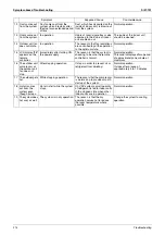
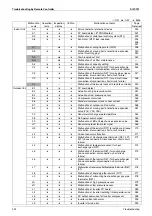
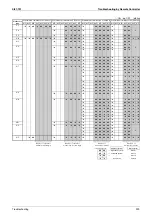
Malfunctions
Malfunction
code
Description of malfunction
Description of malfunction (PGF)
Remote
controller
Open phase and unbalanced power
supply
Unbalanced INV power supply voltage
P1
INV radiation fin temperature sensor
malfunction
INV fin thermistor malfunction
P4
Faulty combination of INV and fan
driver
Faulty combination of INV
PJ
Out of gas
Out-of-gas alarm
U0
Reversed phase
Reversed phase malfunction
U1
Reversed phase malfunction (ON)
Abnormal power supply voltage
Insufficient INV voltage
U2
INV open phase (single phase)
Abnormal charge of capacitor of INV
main circuit
Test run not carried out yet
Test run not carried out yet
U3
Faulty transmission between indoor
and outdoor units
IN-OUT transmission malfunction
U4
System malfunction
Faulty transmission between outdoor
units
Malfunction caused when mounting
the external control adapter
U7
Alarm given when mounting the
external control adapter
Malfunction caused between the
master and the slave 1
Malfunction caused between the
master and the slave 2
Multi REYQ models connected
Faulty address setting of slaves 1 and 2
4 or more outdoor units connected in
the same system
Erroneous address of slaves 1 and 2
Faulty transmission with other
systems
Other system or other unit in the same
system
U9
Faulty field setting
Excess indoor units connected
UA
Erroneous refrigerant used for indoor
unit
Faulty combination of outdoor units
Faulty independent installation
Faulty connection of former BS unit
Faulty connection between outdoor
and BS unit
Faulty connection between BS units
Wrong number of indoor units
connected to BS unit
Faulty system line
Wrong wiring (auto address error)
UH
Faulty transmission with accessory
equipment
Multi level converter malfunction
UJ
Multi level converter alarm
Multi level converter data malfunction
Multi level converter transmission
malfunction
Unmatched wiring/piping, no system
settings
Unmatched wiring/piping
UF
8
: ON
9
: Blink
1
: OFF
Summary of Contents for VRV III REYQ10PY1
Page 1: ...REYQ8 48PY1 R 410A Heat Recovery 50Hz Si37 701 ...
Page 59: ...Specifications Si37 701 48 Specifications ...
Page 105: ...Refrigerant Flow for Each Operation Mode Si37 701 94 Refrigerant Circuit ...
Page 230: ...Si37 701 Troubleshooting by Remote Controller Troubleshooting 219 ...
Page 374: ...Si37 701 Piping Diagrams Appendix 363 REYQ14P 16PY1 3D058153A S2NPL S1NPH ...
Page 375: ...Piping Diagrams Si37 701 364 Appendix REMQ8PY1 3D057743 ...
Page 376: ...Si37 701 Piping Diagrams Appendix 365 REMQ10PY1 12PY1 3D057742 ...
Page 377: ...Piping Diagrams Si37 701 366 Appendix REMQ14PY1 16PY1 3D057741 ...
Page 382: ...Si37 701 Piping Diagrams Appendix 371 1 3 BS Unit 4D057985A ...
Page 384: ...Si37 701 Wiring Diagrams for Reference Appendix 373 REYQ14 16PY1 3D056774C ...
Page 385: ...Wiring Diagrams for Reference Si37 701 374 Appendix REMQ8PY1 3D055307E ...
Page 386: ...Si37 701 Wiring Diagrams for Reference Appendix 375 REMQ10 12PY1 3D055308E ...
Page 387: ...Wiring Diagrams for Reference Si37 701 376 Appendix REMQ14P 16PY1 3D055309E ...
Page 392: ...Si37 701 Wiring Diagrams for Reference Appendix 381 FXCQ40M 50M 80M 125MVE 3D039557A ...
Page 394: ...Si37 701 Wiring Diagrams for Reference Appendix 383 FXZQ20M 25M 32M 40M 50M8V1B 3D038359 ...
Page 395: ...Wiring Diagrams for Reference Si37 701 384 Appendix FXKQ25MA 32MA 40MA 63MAVE 3D039564C ...
Page 399: ...Wiring Diagrams for Reference Si37 701 388 Appendix FXDYQ180M 200M 250MV1 ...
Page 402: ...Si37 701 Wiring Diagrams for Reference Appendix 391 FXMQ200MA 250MAVE 3D039621B ...
Page 403: ...Wiring Diagrams for Reference Si37 701 392 Appendix FXHQ32MA 63MA 100MAVE 3D039801D ...
Page 406: ...Si37 701 Wiring Diagrams for Reference Appendix 395 2 4 BS Unit 3D055928C ...
Page 423: ...Piping Installation Point Si37 701 412 Appendix ...
Page 427: ...Example of Connection R 410A Type Si37 701 416 Appendix ...
Page 433: ...Method of Checking the Inverter s Power Transistors and Diode Modules Si37 701 422 Appendix ...
Page 447: ...Si37 701 iv Index ...

