Si37-701
Index
i
Index
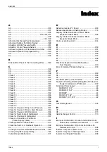
A
A0 .........................................................................230
A1 .........................................................................231
A3 .........................................................................232
A6 .........................................................234, 236, 237
A7 .........................................................................238
A9 .................................................................240, 242
Abnormal Discharge Pipe Temperature ...............263
Abnormal Outdoor Fan Motor Signal ...................268
Actuation of High Pressure Switch .......................251
Actuation of Low Pressure Sensor .......................253
Address Duplication of Centralized Controller .....329
Address Duplication, Improper Setting .................340
AF .........................................................................244
AJ .........................................................................245
B
Broken Wire Check of the Connecting Wires .......352
C
C4 .........................................................................246
C5 .........................................................................247
C9 .........................................................................248
Check 1 ................................................................347
Check 2 ................................................................347
Check 3 ................................................................348
Check 4 ................................................................349
Check 5 ................................................................350
Check 6 ................................................................351
Check 7 ................................................................352
Check 8 ................................................................353
Check 9 ................................................................354
Check 10 ..............................................................355
Check 11 ..............................................................356
Check 12 ..............................................................357
Check 13 ..............................................................358
Check 14 ..............................................................359
Check 15 ..............................................................360
Check for Causes of Drop in Low Pressure .........351
Check for Causes of Rise in High Pressure .........350
Check for Causes of Wet Operation. ...................355
Check for Overcharge of Refrigerant. ..................356
Check for Shortage of Refrigerant. ......................357
Check on Connector of Fan Motor
(Power Supply Cable) ...................................347
Check Operation not Executed ............................310
Check the Factors of Overheat Operation ...........348
CJ .........................................................................249
Concept of Inverter-related Malfunction Codes ....360
Cooling Only/Heat-pump Setting ..........................184
Current Sensor Malfunction .................................271
D
Defective Inverter PC Board ............................... 283
Detailed Explanation of Setting Modes ............... 174
Display “Under Centralized Control” Blinks
(Repeats Double Blink) ................................ 346
Display “Under Centralized Control” Blinks
(Repeats Single Blink) .................................. 343
Drain Level above Limit ....................................... 244
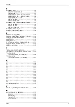
E
E1 ........................................................................ 250
E3 ........................................................................ 251
E4 ........................................................................ 253
E5 ........................................................................ 255
E6 ........................................................................ 257
E7 ........................................................................ 258
E9 ........................................................................ 261
Electronic Expansion Valve Malfunction /
Dust Clogging ............................................... 240
Error of External Protection Device ..................... 230
F
F3 ........................................................................ 263
F6 ........................................................................ 265
F9 ........................................................................ 266
Fan Motor (M1F) Lock, Overload ........................ 234
Faulty Field Setting after Replacing Main PC Board or
Faulty Combination of PC Board .................. 302
Functional Parts Layout ........................................ 62
REMQ10P, 12P .............................................. 65
REMQ14P, 16P .............................................. 66
REMQ8P ......................................................... 64
REYQ14P, 16P ............................................... 63
REYQ8P, 10P, 12P ........................................ 62
G
Gas Shortage Alert .............................................. 304
H
H7 ........................................................................ 268
H9 ........................................................................ 270
Heat Exchanger Control ...................................... 110
I
Improper Combination of Indoor and Outdoor Units,
Indoor Units and Remote Controller ............. 323
Improper Combination of Optional Controllers for
Centralized Control ...................................... 338
Inverter Compressor Motor Lock ......................... 255
Inverter Compressor Starting Failure .................. 292
Inverter Over-Ripple Protection ........................... 298
Summary of Contents for VRV III REYQ10PY1
Page 1: ...REYQ8 48PY1 R 410A Heat Recovery 50Hz Si37 701 ...
Page 59: ...Specifications Si37 701 48 Specifications ...
Page 105: ...Refrigerant Flow for Each Operation Mode Si37 701 94 Refrigerant Circuit ...
Page 230: ...Si37 701 Troubleshooting by Remote Controller Troubleshooting 219 ...
Page 374: ...Si37 701 Piping Diagrams Appendix 363 REYQ14P 16PY1 3D058153A S2NPL S1NPH ...
Page 375: ...Piping Diagrams Si37 701 364 Appendix REMQ8PY1 3D057743 ...
Page 376: ...Si37 701 Piping Diagrams Appendix 365 REMQ10PY1 12PY1 3D057742 ...
Page 377: ...Piping Diagrams Si37 701 366 Appendix REMQ14PY1 16PY1 3D057741 ...
Page 382: ...Si37 701 Piping Diagrams Appendix 371 1 3 BS Unit 4D057985A ...
Page 384: ...Si37 701 Wiring Diagrams for Reference Appendix 373 REYQ14 16PY1 3D056774C ...
Page 385: ...Wiring Diagrams for Reference Si37 701 374 Appendix REMQ8PY1 3D055307E ...
Page 386: ...Si37 701 Wiring Diagrams for Reference Appendix 375 REMQ10 12PY1 3D055308E ...
Page 387: ...Wiring Diagrams for Reference Si37 701 376 Appendix REMQ14P 16PY1 3D055309E ...
Page 392: ...Si37 701 Wiring Diagrams for Reference Appendix 381 FXCQ40M 50M 80M 125MVE 3D039557A ...
Page 394: ...Si37 701 Wiring Diagrams for Reference Appendix 383 FXZQ20M 25M 32M 40M 50M8V1B 3D038359 ...
Page 395: ...Wiring Diagrams for Reference Si37 701 384 Appendix FXKQ25MA 32MA 40MA 63MAVE 3D039564C ...
Page 399: ...Wiring Diagrams for Reference Si37 701 388 Appendix FXDYQ180M 200M 250MV1 ...
Page 402: ...Si37 701 Wiring Diagrams for Reference Appendix 391 FXMQ200MA 250MAVE 3D039621B ...
Page 403: ...Wiring Diagrams for Reference Si37 701 392 Appendix FXHQ32MA 63MA 100MAVE 3D039801D ...
Page 406: ...Si37 701 Wiring Diagrams for Reference Appendix 395 2 4 BS Unit 3D055928C ...
Page 423: ...Piping Installation Point Si37 701 412 Appendix ...
Page 427: ...Example of Connection R 410A Type Si37 701 416 Appendix ...
Page 433: ...Method of Checking the Inverter s Power Transistors and Diode Modules Si37 701 422 Appendix ...
Page 447: ...Si37 701 iv Index ...

