SiBE37-701
Test Operation
Test Operation
183
Setting the mode
The set mode can be changed with the
button according to the following procedure:
For setting mode 1:
Press the
button once, the H1P LED is off
h
. This mode is
not available for heat recovery units.
For setting mode 2:
Press the
button for 5 seconds, the H1P LED is on
i
.
If the H1P LED is blinking
j
and the
button is pushed once, the setting mode will
change to setting mode 1.
Note:
If you get confused in the middle of the setting process, push the
button. Then it
returns to setting mode 1 (H1P LED is off).
Setting mode 2
The H1P LED is on.
Setting procedure
1. Push the
button according to the required function (A~H). The LED indication that
matches the required function is shown below in the field marked
:
2. When the
button is pushed, the current setting is defined.
3. Push the
button according to the required setting possibility as shown below in the
field marked .
3.1Possible settings for function A, B, F, and G are
(ON) or
(OFF).
(a) This setting = factory setting
BS1 MODE
BS1 MODE
BS1 MODE
BS1 MODE
BS1 MODE
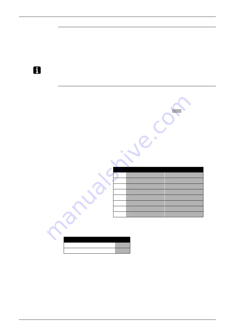
Possible functions
A
additional refrigerant charging operation.
B
refrigerant recovery operation/vacuuming operation.
C
automatic low noise operation setting at nighttime.
D
low noise operation level setting (
) via the external control adapter.
E
power consumption limitation setting (
) via the external control adapter.
F
enabling function of the low noise operation level setting (
) and/or power consumption
limitation setting (
) via the external control adapter (DTA104A61/62).
G
high static pressure setting
H
evaporating temperature setting
H1P
H2P
H3P
H4P
H5P
H6P
H7P
A
i
h
i
h
i
h
h
B
i
h
i
h
i
h
i
C
i
h
i
h
i
i
h
D
i
h
i
i
h
h
i
E
i
h
i
i
i
i
h
F
i
h
h
i
i
h
h
G
i
h
i
h
h
i
h
H
i
h
h
i
h
h
h
H1P H2P H3P H4P H5P H6P H7P
i
h
h
h
h
j
h
(a)
i
h
h
h
h
h
j
BS2 SET
L.N.O.P
DEMAND
L.N.O.P
DEMAND
BS3 RETURN
BS2 SET
ON
OFF
ON
OFF
Summary of Contents for VRV III REYQ10PY1B
Page 1: ...REYQ8 48PY1B R 410A Heat Recovery 50Hz SiBE37 701 ...
Page 111: ...Refrigerant Flow for Each Operation Mode SiBE37 701 100 Refrigerant Circuit ...
Page 252: ...SiBE37 701 Troubleshooting by Remote Controller Troubleshooting 241 ...
Page 396: ...SiBE37 701 Piping Diagrams Appendix 385 REYQ14P 16P 3D058153B S2NPL S1NPH ...
Page 397: ...Piping Diagrams SiBE37 701 386 Appendix REMQ8P 3D057743 ...
Page 398: ...SiBE37 701 Piping Diagrams Appendix 387 REMQ10P 12P 3D057742 ...
Page 399: ...Piping Diagrams SiBE37 701 388 Appendix REMQ14P 16P 3D057741 ...
Page 400: ...SiBE37 701 Piping Diagrams Appendix 389 1 2 Indoor Unit FXFQ P ...
Page 405: ...Piping Diagrams SiBE37 701 394 Appendix 1 3 BS Unit 4D057985A ...
Page 415: ...Wiring Diagrams for Reference SiBE37 701 404 Appendix FXZQ20M 25M 32M 40M 50MV1 ...
Page 416: ...SiBE37 701 Wiring Diagrams for Reference Appendix 405 FXCQ20M 25M 32M 63MV3 ...
Page 417: ...Wiring Diagrams for Reference SiBE37 701 406 Appendix FXCQ40M 50M 80M 125MV3 ...
Page 420: ...SiBE37 701 Wiring Diagrams for Reference Appendix 409 FXDQ20M 25MV3 ...
Page 421: ...Wiring Diagrams for Reference SiBE37 701 410 Appendix FXSQ20M 25M 32M 40M 50M 63MV3 ...
Page 422: ...SiBE37 701 Wiring Diagrams for Reference Appendix 411 FXSQ80M 100M 125MV3 ...
Page 447: ...Example of connection SiBE37 701 436 Appendix ...
Page 453: ...Method of Checking the Inverter s Power Transistors and Diode Modules SiBE37 701 442 Appendix ...
Page 467: ...SiBE37 701 iv Index ...


