SiBE37-701
Troubleshooting by Indication on the Remote Controller
Troubleshooting
321
Troubleshooting
(V2816)
Caution
Be sure to turn off power switch before connect or disconnect connector,
or parts damage may be occurred.
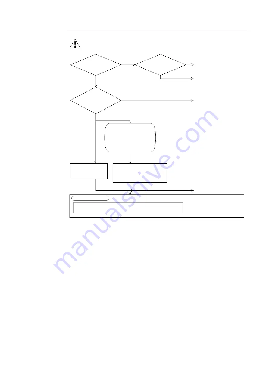
Is
the voltage
imbalance applied to the
inverter in excess of
14 V (Y1)?
∗
2
NO
Part or wiring defect
After turning the power supply
OFF, check and repair the
main circuit wiring or parts.
(1) Loose or disconnected
wiring between power
supply and inverter
(2) K2 contact disposition,
fusion or contact is poor.
(3) Loose or disconnected
noise filter
Using a device capable of
constant recording of power
supply voltage record
power supply voltage
between 3 phases (L1 ~ L2,
L2 ~ L3, L3~L1) for about
one continuous week.
Open phase
Normalize field cause.
Power supply voltage imbalance
Even if the power supply voltage is not
unbalanced when measuring it, there are
many cases where it gets unbalanced during
nighttime (around 6:00PM to 10:00PM).
No abnormalities are
observed in the power
supply, but the imbalance
in voltage recurs.
Explanation for users
Fix power supply voltage
imbalance.
Replace the inverter PC board.
YES
YES
NO
Imbalance
in supplied voltage is
in excess of 14 V
(Y1).
∗
1
Open phase?
<When voltage monitoring is possible:>
∗
1. Measure voltage at the X1M power supply
terminal block.
∗
2. Measure voltage at connector X10A (RED,
WHITE and BLACK wire pins) of the diode
module inside the inverter while the compressor
is running.
∗
In accordance with "notification of inspection results" accompanying spare parts.
Give the user a copy of "notification of inspection results"and leave
it up to him to improve the imbalance.
Be sure to explain to the user that
there is a "power supply imbalance"
for which DAIKIN is not responsible.
measure
YES
NO
Summary of Contents for VRV III REYQ10PY1B
Page 1: ...REYQ8 48PY1B R 410A Heat Recovery 50Hz SiBE37 701 ...
Page 111: ...Refrigerant Flow for Each Operation Mode SiBE37 701 100 Refrigerant Circuit ...
Page 252: ...SiBE37 701 Troubleshooting by Remote Controller Troubleshooting 241 ...
Page 396: ...SiBE37 701 Piping Diagrams Appendix 385 REYQ14P 16P 3D058153B S2NPL S1NPH ...
Page 397: ...Piping Diagrams SiBE37 701 386 Appendix REMQ8P 3D057743 ...
Page 398: ...SiBE37 701 Piping Diagrams Appendix 387 REMQ10P 12P 3D057742 ...
Page 399: ...Piping Diagrams SiBE37 701 388 Appendix REMQ14P 16P 3D057741 ...
Page 400: ...SiBE37 701 Piping Diagrams Appendix 389 1 2 Indoor Unit FXFQ P ...
Page 405: ...Piping Diagrams SiBE37 701 394 Appendix 1 3 BS Unit 4D057985A ...
Page 415: ...Wiring Diagrams for Reference SiBE37 701 404 Appendix FXZQ20M 25M 32M 40M 50MV1 ...
Page 416: ...SiBE37 701 Wiring Diagrams for Reference Appendix 405 FXCQ20M 25M 32M 63MV3 ...
Page 417: ...Wiring Diagrams for Reference SiBE37 701 406 Appendix FXCQ40M 50M 80M 125MV3 ...
Page 420: ...SiBE37 701 Wiring Diagrams for Reference Appendix 409 FXDQ20M 25MV3 ...
Page 421: ...Wiring Diagrams for Reference SiBE37 701 410 Appendix FXSQ20M 25M 32M 40M 50M 63MV3 ...
Page 422: ...SiBE37 701 Wiring Diagrams for Reference Appendix 411 FXSQ80M 100M 125MV3 ...
Page 447: ...Example of connection SiBE37 701 436 Appendix ...
Page 453: ...Method of Checking the Inverter s Power Transistors and Diode Modules SiBE37 701 442 Appendix ...
Page 467: ...SiBE37 701 iv Index ...


