Special Control
Si34-601A
116
Function
3.7
Stopping Operation
3.7.1 When System is in Stop Mode (Normal operation stop)
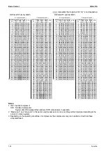
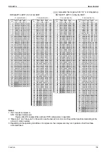
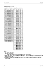
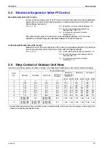
This mode is used to define actuator operations when the system stops.
*
Actuators are based on RXYQ14~18P.
3.7.2 Stop due to Malfunction
In order to protect compressors, if any of the following items has an abnormal value, the system will make "stop with
thermostat OFF" and the malfunction will be determined according to the number of retry times.
Actuator
Operation
Compressor
OFF
Outdoor unit fan
OFF
Four way valve
Holds
Main motorized valve (EV1)
0 pls
Subcooling motorized valve (EV2)
0 pls
Hot gas bypass valve (SVP)
OFF
Accumulator oil return valve (SVO)
OFF
Injection (SVT) (RXYQ5P model only)
OFF
Ending conditions
Indoor unit thermostat is turned ON.
Item
Judgment Criteria
Malfunction Code
1. Abnormal low pressure level
0.07MPa
E4
2. Abnormal high pressure level
4.0MPa
E3
3. Abnormal discharge pipe temperature level
135
°
C
F3
4. Abnormal power supply voltage
Reverse-phase power supply
U1
5. Abnormal inverter current level
16.1A: 260 sec.
L8
6. Abnormal radiator fin temperature level
93
°
C
L4
Summary of Contents for VRV III RXYQ5-54PY1
Page 1: ...RXYQ5 54PY1 R 410A Heat Pump 50Hz Si34 601A...
Page 101: ...Refrigerant Flow for Each Operation Mode Si34 601A 90 Refirgerant Circuit...
Page 153: ...Outline of Control Indoor Unit Si34 601A 142 Function...
Page 219: ...Troubleshooting by Remote Controller Si34 601A 208 Troubleshooting...
Page 226: ...Si34 601A Troubleshooting by Remote Controller Troubleshooting 215...
Page 325: ...Troubleshooting OP Unified ON OFF Controller Si34 601A 314 Troubleshooting...
Page 327: ...Piping Diagrams Si34 601A 316 Appendix 1 Piping Diagrams 1 1 Outdoor Unit RXYQ5PY1 3D050782...
Page 328: ...Si34 601A Piping Diagrams Appendix 317 RXYQ8P 3D050783...
Page 329: ...Piping Diagrams Si34 601A 318 Appendix RXYQ10P 12PY1 3D050784...
Page 330: ...Si34 601A Piping Diagrams Appendix 319 RXYQ14P 16P 18PY1 3D050785...
Page 336: ...Si34 601A Wiring Diagrams for Reference Appendix 325 RXYQ8PY1 3D050454J...
Page 337: ...Wiring Diagrams for Reference Si34 601A 326 Appendix RXYQ10PY1 3D050455H...
Page 338: ...Si34 601A Wiring Diagrams for Reference Appendix 327 RXYQ12PY1 3D051890G...
Page 339: ...Wiring Diagrams for Reference Si34 601A 328 Appendix RXYQ14P 16P 18PY1 3D050456H...
Page 344: ...Si34 601A Wiring Diagrams for Reference Appendix 333 FXCQ40M 50M 80M 125MVE 3D039557A...
Page 346: ...Si34 601A Wiring Diagrams for Reference Appendix 335 FXZQ20M 25M 32M 40M 50M7V1B 3D038359...
Page 347: ...Wiring Diagrams for Reference Si34 601A 336 Appendix FXKQ25MA 32MA 40MA 63MAVE 3D039564C...
Page 352: ...Si34 601A Wiring Diagrams for Reference Appendix 341 FXMQ200MA 250MAVE 3D039621B...
Page 353: ...Wiring Diagrams for Reference Si34 601A 342 Appendix FXHQ32MA 63MA 100MAVE 3D039801D...
Page 356: ...Si34 601A Wiring Diagrams for Reference Appendix 345 FXUQ71MA 100MA 125MAV1 3D044973A...
Page 357: ...Wiring Diagrams for Reference Si34 601A 346 Appendix FXMQ125MF 200MF 250MFV1 3D044996C...
Page 358: ...Si34 601A Wiring Diagrams for Reference Appendix 347 BEVQ71MA 100MA 125MAVE 3D044901B...
Page 381: ...Method of Checking The Inverter s Power Transistors and Diode Modules Si34 601A 370 Appendix...
Page 395: ...Si34 601A iv Index...


