background image

16 Configuration

Installation and operation manual

34

RK RKXYQ8T7Y1B

VRV IV compressor unit for indoor installation

4P499900-1B – 2021.12

Setting

Value

(8 HP)

(5 HP)

Description

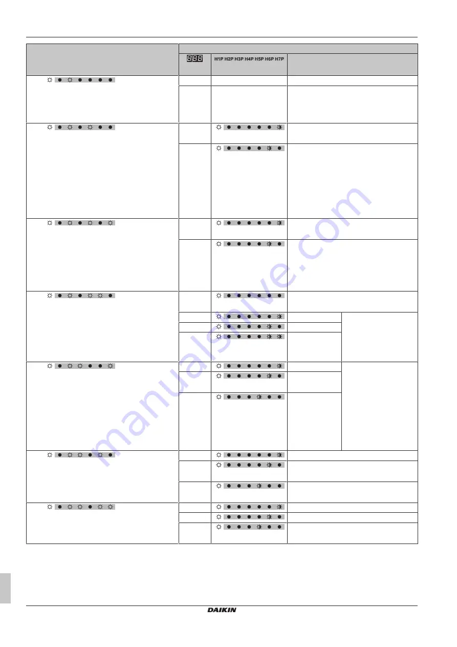
[2‑16] 

Test run heat exchanger unit.

When activated, the heat exchanger fans start running.
This allows you to check the ducting with a running
heat exchanger unit.

0 (default)

Deactivated.

1

Activated.

[2‑20] 

Manual additional refrigerant charge.

In order to add the additional refrigerant charge
amount in a manual way (without automatic refrigerant
charging functionality), following setting should be
applied.

0 (default)

(= binary 1) (default)

Deactivated.

1

(= binary 2)

Activated.

To stop the manual additional refrigerant
charge operation (when the required additional
refrigerant amount is charged), push BS3. If
this function was not aborted by pushing BS3,
the unit will stop its operation after 30 minutes.
If 30 minutes was not sufficient to add the
needed refrigerant amount, the function can be
reactivated by changing the field setting again.

[2‑21] 

Refrigerant recovery/vacuuming mode.

In order to achieve a free pathway to reclaim
refrigerant out of the system or to remove residual
substances or to vacuum the system it is necessary to
apply a setting which will open required valves in the
refrigerant circuit so the reclaim of refrigerant or
vacuuming process can be done properly.

0 (default)

(= binary 1) (default)

Deactivated.

1

(= binary 2)

Activated.

To stop the refrigerant recovery/vacuuming
mode, push BS1 (in case of 5 HP) or BS3 (in
case of 8 HP). If it is not pushed, the system
will remain in refrigerant recovery/vacuuming
mode.

[2‑22] 

Automatic low noise setting and level during night time.

By changing this setting, you activate the automatic
low noise operation function of the unit and define the
level of operation. Depending on the chosen level, the
noise level will be lowered. The start and stop
moments for this function are defined under setting
[2‑26] and [2‑27].

0 (default)

(default)

Deactivated

1

Level 1

Level 3<Level 2<Level 1

2

Level 2

3

Level 3

[2‑25] 

Low noise operation level via the external control
adaptor.

If the system needs to be running under low noise
operation conditions when an external signal is sent to
the unit, this setting defines the level of low noise that
will be applied.

This setting will only be effective when the optional
external control adaptor (DTA104A61/62) is installed
and the setting [2‑12] was activated.

1

Level 1

Level 3<Level 2<Level 1

2 (default)

(default)

Level 2

3

(= binary 4)

Level 3

[2‑26] 

Low noise operation start time.

This setting is used in conjunction with setting [2‑22].

1

20h00

2 (default)

(default)

22h00

3

(= binary 4)

24h00

[2‑27] 

Low noise operation stop time.

This setting is used in conjunction with setting [2‑22].

1

6h00

2

7h00

3 (default)

(= binary 4) (default)

8h00

Summary of Contents for VRV IV i Series

Page 1: ...Installation and operation manual VRV IV compressor unit for indoor installation English Installation and operation manual VRV IV compressor unit for indoor installation RKXYQ5T8Y1B RKXYQ8T7Y1B...

Page 2: ...z na imi navodili on vastavuses j rgmis t e standardi te ga v i teiste normatiivsete dokumentidega kui neid kasutatakse vastavalt meie juhenditele atitinka emiau nurodytus standartus ir arba kitus nor...

Page 3: ...d senere ndringer Direktiv med f retagna ndringar Direktiver med foretatte endringer Direktiivej sellaisina kuin ne ovat muutettuina v platn m zn n Smjernice kako je izmijenjeno ir nyelv ek s m dos t...

Page 4: ...S vastaava kyll stysl mp tila M C Kylm aine N Varmuuspainelaitteen asetus P bar Valmistusnumero ja valmistusvuosi katso mallin nimikilpi Maxim ln p pustn tlak PS K bar Minim ln maxim ln p pustn teplot...

Page 5: ...door unit fan does not spin 15 8 2 15 Symptom The display shows 88 15 8 2 16 Symptom The compressor in the outdoor unit does not stop after a short heating operation 15 8 2 17 Symptom The inside of an...

Page 6: ...nstaller and user reference guide Preparation of the installation reference data Detailed step by step instructions and background information for basic and advanced usage Format Digital files on http...

Page 7: ...rter A phase advancing capacitor will reduce performance and may cause accidents WARNING All wiring MUST be performed by an authorised electrician and MUST comply with the applicable legislation Make...

Page 8: ...unsorted household waste If a chemical symbol is printed beneath the symbol this chemical symbol means that the battery contains a heavy metal above a certain concentration Possible chemical symbols a...

Page 9: ...er such circumstances may cause breakage electrical shock or fire Contact your dealer WARNING The refrigerant in the system is safe and normally does NOT leak If the refrigerant leaks in the room cont...

Page 10: ...fter the heating operation stops The air flow rate may adjust itself depending on the room temperature or the fan may stop immediately This is not a malfunction 6 2 3 About the heating operation It ma...

Page 11: ...only for double flow multi flow corner ceiling suspended and wall mounted Refer to 6 4 Adjusting the air flow direction 411 for details To stop 4 Press the ON OFF button on the user interface once aga...

Page 12: ...nsert fingers rods or other objects into the air inlet or outlet Do NOT remove the fan guard When the fan is rotating at high speed it will cause injury CAUTION After a long use check the unit stand a...

Page 13: ...or breaker is activated Change the fuse or reset the breaker if necessary Malfunction Measure If the system goes into fan only operation but as soon as it goes into heating or cooling operation the sy...

Page 14: ...on centralised control device indoor unit Auto address malfunction inconsistency Auto address malfunction inconsistency 8 2 Symptoms that are NOT system malfunctions The following symptoms are NOT sys...

Page 15: ...is the sound of refrigerant gas flowing through both indoor and outdoor units A hissing sound which is heard at the start or immediately after stopping operation or defrost operation This is the noise...

Page 16: ...quid 9 5 mm 9 5 mm e Piping adapter 19 1 22 2 mm that you need when connecting piping to the heat exchanger unit only for 8 HP 11 1 2 To remove the transportation stay Only for RKXYQ5 NOTICE If the un...

Page 17: ...s for the compressor unit and heat exchanger unit For more possible options see the installer and user reference guide Cool heat selector In order to control the cooling or heating operation from a ce...

Page 18: ...SK OF BURNING SCALDING DANGER RISK OF ELECTROCUTION 1 Remove the service cover of the compressor unit 5 5 5 HP 8 HP 2 If you want to make field settings remove the inspection cover 5 HP 8 HP 3 If you...

Page 19: ...ameters mm sizes taken the following into account Select the pipe size nearest to the required size Use the suitable adapters for the change over from inch to mm pipes field supply The additional refr...

Page 20: ...unit b Compressor unit c Refrigerant branch kit VRV DX VRV DX indoor unit EKEXV Expansion valve kit AHU Air handling unit H1 H5 Height differences L1 L7 Piping lengths Minimum and maximum piping leng...

Page 21: ...B C C C D D RDXYQ RDXYQ c c d d b b a a 5 HP 8 HP Method 2 First connect to the first 2 service ports C C b B a A Then connect to the last 2 service ports d B c A C C a b c d Service ports of stop va...

Page 22: ...cause malfunctions smoke or fire 14 3 Checking the refrigerant piping 14 3 1 About checking the refrigerant piping Refrigerant piping works are finished The indoor units compressor unit and or heat ex...

Page 23: ...e splitters to both circuits and check Without refrigerant line splitters takes twice as long You have to check the circuits separately To do so First connect the manifold to circuit 1 and check Then...

Page 24: ...ing according to the installation environment Ambient temperature Humidity Minimum thickness 30 C 75 to 80 RH 15 mm 30 C 80 RH 20 mm If there is a possibility that condensation on the stop valve might...

Page 25: ...C C d B c A a Liquid line stop valve circuit 1 to heat exchanger unit b Gas line stop valve circuit 1 to heat exchanger unit c Gas line stop valve circuit 2 to indoor units d Liquid line stop valve ci...

Page 26: ...unction code and take corresponding action 19 1 Solving problems based on error codes 438 14 4 5 To fix the fluorinated greenhouse gases label 1 Fill in the label as follows b Contains fluorinated gre...

Page 27: ...tween the compressor unit the heat exchanger unit and the indoor units Example g f F1 F2 16 V F1 F2 16 V 220 240 V 1 50 Hz e c a d b 220 240 V 1 50 Hz 380 415 V 3N 50 Hz a Main switch b Earth connecti...

Page 28: ...he left side of the switch box 1 c 50 mm a b b X1M L1 F1F2 L2 L3 N c a c X2M A1P b a X1M X2M 5 HP 50 mm a b b a X1M X1M A1P X1M b a c c 8 HP X1M A1P c a Transmission wiring b Power supply c Cable tie...

Page 29: ...ing components See 13 2 1 To open the compressor unit 418 16 1 3 Field setting components The components to make field settings differ depending on the model Model Field setting components 5 HP Push b...

Page 30: ...ot displayed after 10 12 minutes check the malfunction code on the indoor unit user interface and in case of 8 HP on the compressor unit 7 segment display Solve the malfunction code accordingly First...

Page 31: ...HP You can change the value of setting 2 8 Te target temperature during cooling operation to 4 8 C as follows Action Button display 1 Start from the default situation 2 Select mode 2 BS1 5 s 3 Select...

Page 32: ...1 16 Shows the 3rd last malfunction code 7 segments display Mode 1 in case of 8 HP You can read out the following information Setting Value Description 1 1 Shows the status of low noise operation 0 Un...

Page 33: ...ay and the settings differ depending on the model Model Display Setting value 5 HP 7 LEDs display The seven LEDs give a binary representation of the setting value number 8 HP 7 segments display The th...

Page 34: ...so the reclaim of refrigerant or vacuuming process can be done properly 0 default binary 1 default Deactivated 1 binary 2 Activated To stop the refrigerant recovery vacuuming mode push BS1 in case of...

Page 35: ...is setting defines the level power consumption limitation that will be applied for step 2 The level is according to the table binary 1 30 1 default binary 2 default 40 2 binary 4 50 3 55 2 32 Forced a...

Page 36: ...pplicable legislation Power supply voltage Check the power supply voltage on the local supply panel The voltage MUST correspond to the voltage on the nameplate of the unit Earth wiring Be sure that th...

Page 37: ...mode 1 or 2 430 Push BS4 for 5 seconds or more The unit will start test operation Result The test operation is automatically carried out the compressor unit H2P flashes and the indication Test operati...

Page 38: ...it 19 Troubleshooting 19 1 Solving problems based on error codes In case of a displayed malfunction code perform correcting actions as explained in the malfunction code table After correcting the abno...

Page 39: ...ction open circuit short circuit Compressor unit BIPH A1P X17A Check connection on PCB or actuator Low pressure sensor malfunction open circuit short circuit Compressor unit BIPL A1P X18A Check connec...

Page 40: ...sion valve malfunction subcool Compressor unit Y1E A1P X21A Check connection on PCB or actuator Electronic expansion valve malfunction main Heat exchanger unit Y1E A1P X7A Check connection on PCB or a...

Page 41: ...g to Q1 Q2 or indoor outdoor Check Q1 Q2 wiring Do NOT use Q1 Q2 Faulty wiring to Q1 Q2 or indoor outdoor Check Q1 Q2 wiring Do NOT use Q1 Q2 System test run abnormal ending Execute test run again War...

Page 42: ...3E R2T M1C R3T R7T R4T Y1S S1NPL S1PH S1NPH R5T f f l c b f g a d f m h f i j k e B A 3D110524 1 A Heat exchanger unit B Compressor unit a Stop valve gas circuit 2 to indoor units b Stop valve liquid...

Page 43: ...umulator R4T Thermistor subcool heat exchanger gas R5T Thermistor suction compressor R7T Thermistor liquid R10T Thermistor fin S1NPL Low pressure sensor S1NPH High pressure sensor S1PH High pressure s...

Page 44: ...e module A3P X37A Connector power supply for option PCB optional X66A Connector cool heat selector switch optional X1M Terminal strip power supply X A PCB connector X M Terminal strip on PCB A P X Y C...

Page 45: ......

Page 46: ......

Page 47: ......

Page 48: ...4P499900 1B 2021 12 Copyright 2017 Daikin 4P499900 1 B 00000002 Verantwortung f r Energie und Umwelt...

Reviews: