5 User interface
Installation and operation manual
10
RK RKXYQ8T7Y1B
VRV IV compressor unit for indoor installation
4P499900-1B – 2021.12
5
User interface
CAUTION
▪ NEVER touch the internal parts of the controller.
▪ Do NOT remove the front panel. Some parts inside are
dangerous to touch and appliance problems may
happen. For checking and adjusting the internal parts,
contact your dealer.
This operation manual offers a non-exhaustive overview of the main
functions of the system.
Detailed information on required actions to achieve certain functions
can be found in the dedicated installation and operation manual of
the indoor unit.
Refer to the operation manual of the installed user interface.
6
Operation
6.1
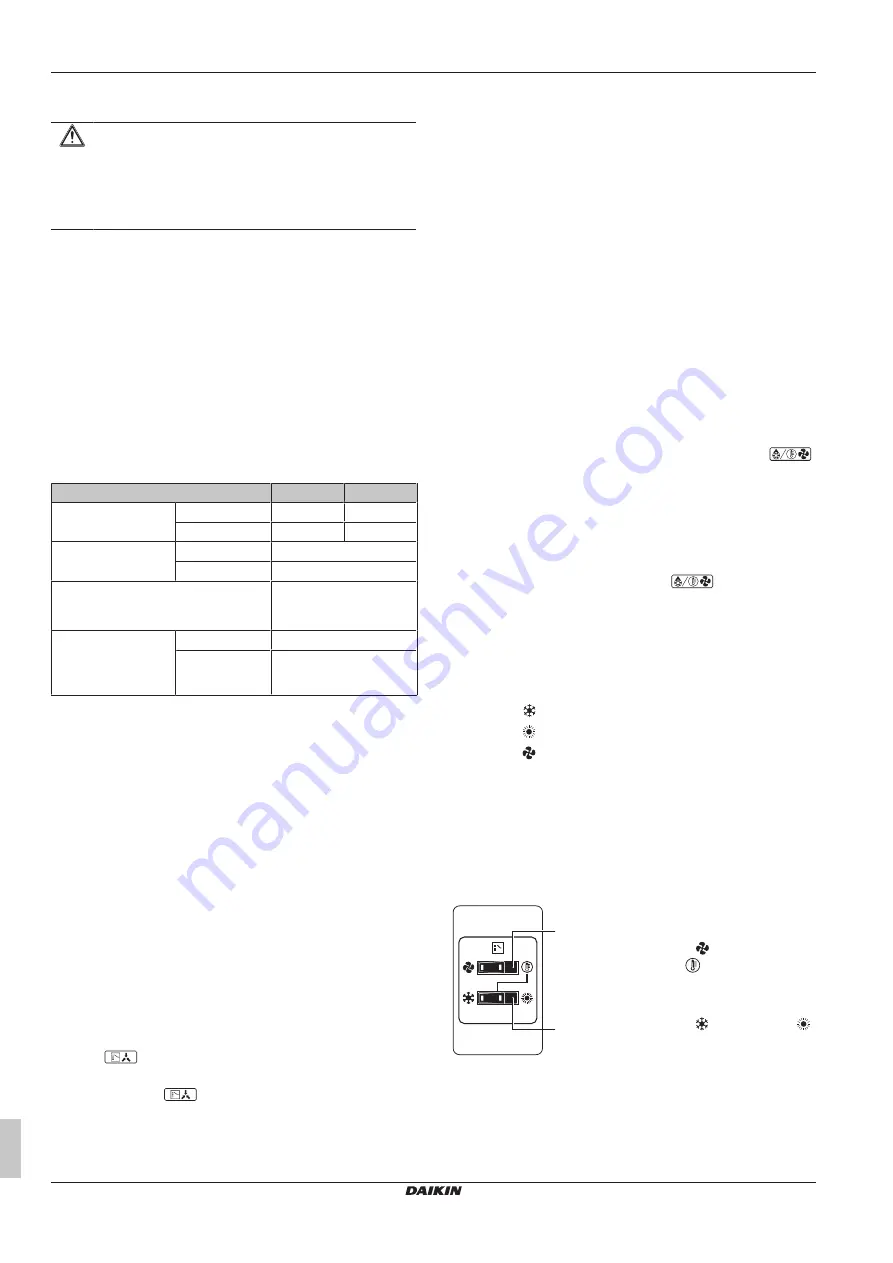
Operation range
Use the system in the following temperature and humidity ranges for
safe and effective operation.
Specification
5 HP
8 HP
Maximum capacity
Heating
16.0 kW
25.0 kW
Cooling
14.0 kW
22.4 kW
Outside ambient
design temperature
Heating
–20~15.5°C WB
Cooling
–5~46°C DB
Ambient design temperature of
compressor unit and heat exchanger
unit
5~35°C DB
Maximum relative
humidity around the
compressor unit and
heat exchanger unit
Heating
50%
(a)
Cooling
80%
(a)
Special operation ranges are valid in case of using AHU. They can
be found in the installation/operation manual of the dedicated unit.
Latest information can be found in the technical engineering data.
6.2
Operating the system
6.2.1
About operating the system
▪ Operation procedure varies according to the combination of
compressor unit, heat exchanger unit, and user interface.
▪ To protect the unit, turn on the main power switch 6 hours before
operation.
▪ If the main power supply is turned off during operation, operation
will restart automatically after the power turns back on again.
▪ When stopping the unit, the unit might still operate for a few
minutes. This is not a malfunction.
6.2.2
About cooling, heating, fan only, and
automatic operation
▪ Changeover cannot be made with a user interface whose display
shows
"change-over under centralised control" (refer to
installation and operation manual of the user interface).
▪ When the display
"change-over under centralised control"
flashes, refer to
"6.5.1 About setting the master user
12].
▪ The fan may keep on running for about 1 minute after the heating
operation stops.
▪ The air flow rate may adjust itself depending on the room
temperature or the fan may stop immediately. This is not a
malfunction.
6.2.3
About the heating operation
It may take longer to reach the set temperature for general heating
operation than for cooling operation.
The following operation is performed in order to prevent the heating
capacity from dropping or cold air from blowing.
Defrost operation
In heating operation, freezing of the heat exchanger unit's air cooled
coil increases over time, restricting the energy transfer to the heat
exchanger unit's coil. Heating capability decreases and the system
needs to go into defrost operation to be able to remove frost from the
heat exchanger unit's coil. During defrost operation the heating
capacity on the indoor unit side will temporarily drop until defrosting
is completed. After defrosting, the unit will regain its full heating
capacity.
The indoor unit will stop fan operation, the refrigerant cycle will
reverse and energy from inside the building will be used to defrost
the heat exchanger unit coil.
The indoor unit will indicate defrost operation on the display
.
During defrost operation, ice melts and possibly evaporates.
Possible consequence:
Mist might be visible during or directly after
defrost operation. This is not a malfunction.
Hot start
In order to prevent cold air from blowing out of an indoor unit at the
start of heating operation, the indoor fan is automatically stopped.
The display of the user interface shows
. It may take some
time before the fan starts. This is not a malfunction.
6.2.4
To operate the system (WITHOUT cool/
heat changeover remote control switch)
1
Press the operation mode selector button on the user interface
several times and select the operation mode of your choice.
Cooling operation
Heating operation
Fan only operation
2
Press the ON/OFF button on the user interface.
Result:
The operation lamp lights up and the system starts
operating.
6.2.5
To operate the system (WITH cool/heat
changeover remote control switch)
Overview of the changeover remote control switch
a
b
a
FAN ONLY/AIR CONDITIONING
SELECTOR SWITCH
Set the switch to
for fan only
operation or to
for heating or
cooling operation.
b
COOL/HEAT CHANGEOVER SWITCH
Set the switch to
for cooling or to
for heating
Note:
In case a cool/heat changeover remote control switch is used,
the position of DIP switch 1 (DS1-1) on the main PCB needs to be
switched to the ON position.


